
-
- Products
- Indoor Household Cords
- Appliance Cords
- General Purpose Short-Length Cords
- General Purpose Extension Cords
- Landscape & Decorating Cords
- Bright Color Extension Cords
- Oil-Resistant Extension Cords
- Cold-Flex Extension Cords
- VividFlex Power Cords
- EXTREME All-Weather Cords
- Cord Management
- Task Lights
- Adapters & GFCI Devices
- Where to Buy
- About
- Careers
- Glossary
- Catalog


125 Amp MCCB Best Choice for Global Buyers?
Global electrical systems are becoming more demanding, yet buyers still need practical protection rather than impressive specifications. The International Energy Agency’s Electricity 2024 report projects global electricity demand to grow by an average of 3.2% annually from 2024 to 2026. That growth increases pressure on commercial buildings, factories, data centers, and renewable-energy installations. In these applications, a 125amp Mccb can provide a useful balance between feeder protection, installation space, and operating capacity.
But “best choice” is never determined by amperage alone. A 125 A molded case circuit breaker must match the system voltage, pole configuration, interrupting capacity, trip characteristics, and available fault current. IEC 60947-2 defines important requirements for low-voltage circuit breakers, while UL 489 is widely referenced in North American installations. Buyers should also compare Icu, Ics, short-circuit current ratings, temperature derating, and accessory compatibility. Small details matter. A cramped panel can turn routine maintenance into a costly interruption.
Market research often reports steady growth in circuit-breaker demand, driven by grid upgrades, industrial automation, and renewable integration. However, market forecasts do not replace engineering verification. A product may perform well in one region but fail a local certification or coordination review. That assumption deserves testing. Experienced purchasers should request test certificates, factory quality records, datasheets, and traceable production information. The right 125amp Mccb is therefore not simply the cheapest or most powerful option. It is the model that fits the complete electrical design, installation environment, and compliance requirements. Mistakes remain possible, especially when product labels hide important rating differences.
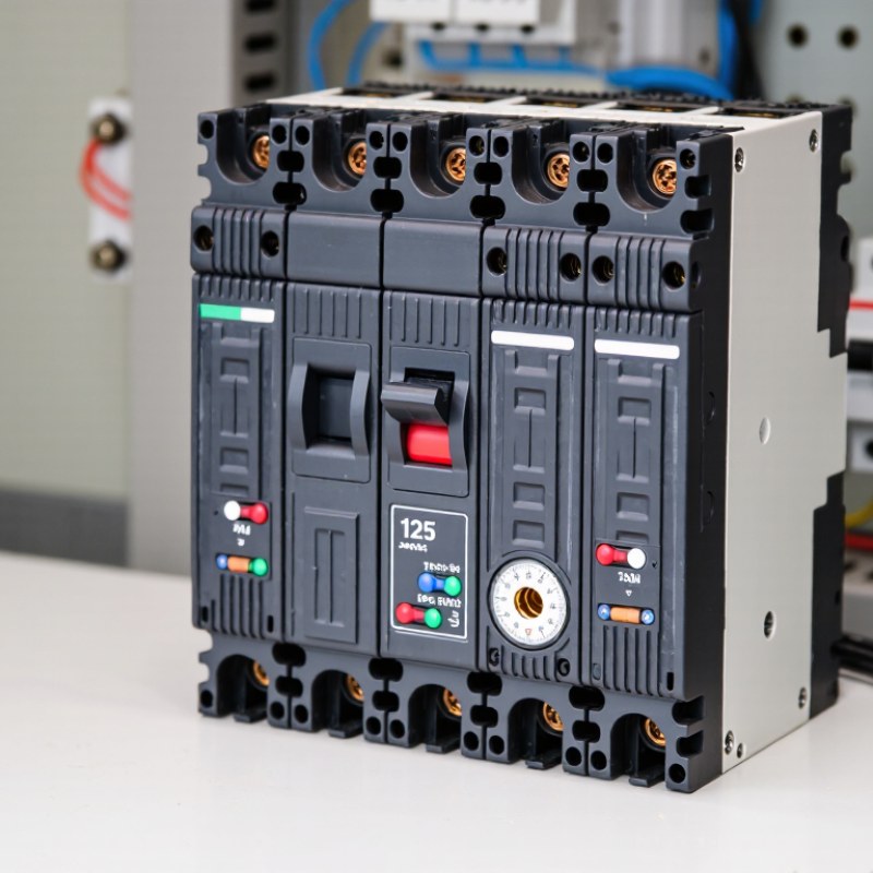
Table of Contents [Hide]
What Is a 125 Amp MCCB and How Does It Work?
A 125 amp MCCB is a molded case circuit breaker designed to carry up to 125 amperes under specified conditions. It protects cables, motors, and distribution panels from overloads and short circuits. The 125 amp rating is not a universal promise. Ambient temperature, enclosure size, installation method, and conductor selection can affect safe operation.
Inside the breaker, a thermal element responds to prolonged overcurrent. A bimetal strip heats, bends, and releases the trip mechanism. This action usually takes time, allowing brief starting currents to pass. During a short circuit, the magnetic element reacts almost instantly. It separates the contacts and sends the fault current into an arc-extinguishing chamber. The handle may move to a tripped position. After inspection, the breaker can normally be reset manually.
A practical selection needs more than the current rating. Check the system voltage, number of poles, frequency, interrupting capacity, and trip adjustment range. The interrupting rating must exceed the available fault current at the installation point. Cable ampacity and coordination with upstream and downstream protection also matter. In a warm, crowded panel, a 125 amp breaker may carry less than expected because heat cannot escape easily. That detail is often missed. A 125 amp label is not a complete selection. Local electrical standards should guide final approval, and a qualified engineer should verify the design before energizing the circuit.