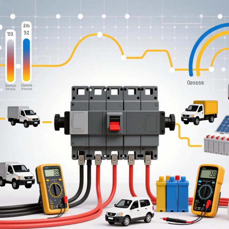
| DC Voltage Architecture | Common ratings include 250 VDC, 500 VDC, 750 VDC, 1,000 VDC, and 1,500 VDC, depending on the pole configuration and product design. | Series-connected poles and suitable creepage and clearance distances are used to withstand the required DC voltage and interrupt the arc safely. | Insulation-system verification, dielectric withstand testing, polarity checks, and clearance measurement are required during design validation. | IEC 60947-2; UL 489 for applicable products |
| Continuous Current Rating | Typical molded-case product families cover approximately 15 A to 1,600 A; higher ratings require larger frames or specialized construction. | The frame size, conductor cross-section, contact system, and thermal path are selected according to the rated current and installation environment. | Temperature-rise testing is performed at the rated current. Terminal torque, busbar interface, and enclosure heat dissipation are controlled. | IEC 60947-2 temperature-rise requirements |
| Interrupting Technology | DC short-circuit interrupting capacities commonly range from several kiloamperes to more than 50 kA, depending on voltage and frame size. | Magnetic blowout, arc runners, splitter plates, and optimized arc chambers lengthen, cool, and de-ionize the DC arc. | Short-circuit tests are conducted at the declared voltage, current, time constant, and polarity. Post-test insulation and operating checks are required. | IEC 60947-2 short-circuit performance categories |
| Arc-Quenching System | Arc chambers typically use heat-resistant insulating barriers, metal splitter plates, arc runners, and magnetic-field control. | Because DC has no natural current zero, the arc-quenching structure must force rapid arc elongation and energy absorption. | Material selection, plate spacing, ventilation paths, and resistance to erosion are verified through endurance and interruption testing. | DC-specific interruption validation under IEC 60947-2 |
| Trip-Unit Technology | Thermal-magnetic, electronic, and microprocessor-based trip units are common. Adjustable long-time and instantaneous settings are available on many electronic designs. | Electronic trip units improve protection accuracy and may provide overload, short-circuit, ground-fault, alarm, and communication functions. | Calibration, sensor accuracy, trip-time verification, electromagnetic compatibility, and firmware control are checked before shipment. | IEC 60947-2 trip characteristics; applicable EMC requirements |
| Current Sensing | Low-resistance shunts, magnetic sensors, or current transformers are selected according to the DC current range and protection algorithm. | Accurate sensing allows the trip unit to distinguish overload conditions from high-magnitude short circuits. | Sensor linearity, thermal drift, polarity, wiring integrity, and calibration points are verified across the operating range. | Product-specific protection and measurement specifications |
| Thermal Management | Copper or copper-alloy current paths, silver-alloy contact materials, and thermally stable insulating materials are commonly used. | Low-resistance joints reduce power loss and limit temperature rise during continuous operation. | Contact resistance, torque values, terminal temperature rise, material consistency, and enclosure ventilation are controlled. | IEC 60947-1 and IEC 60947-2 temperature-rise tests |
| Main Contact System | Fixed and moving contacts are designed for low contact resistance, adequate contact pressure, and resistance to welding during faults. | Contact geometry and spring force support reliable current transfer, fast opening, and stable performance over repeated operations. | Contact alignment, contact force, surface finish, weld resistance, and mechanical endurance are inspected. | Mechanical and electrical endurance requirements in IEC 60947-2 |
| Molded Insulation Housing | Thermoset or thermoplastic insulating compounds are selected for dielectric strength, flame resistance, mechanical strength, and dimensional stability. | The housing provides insulation, supports the operating mechanism, guides the arc chamber, and protects internal parts from dust and accidental contact. | Flammability, impact strength, dimensional accuracy, insulation resistance, and resistance to heat and moisture are evaluated. | IEC 60695 fire-hazard methods; IEC 60947 insulation requirements |
| Polarity and Connection Design | Two-pole, three-pole, and four-pole configurations are used according to system voltage, grounding method, and isolation requirements. | Correct polarity and current-direction markings are essential because many DC breakers use directional magnetic and arc-control structures. | Polarity marking, terminal identification, wiring diagrams, and reverse-connection behavior are verified during inspection. | IEC 60947-2 connection and marking provisions |
| Isolation Function | A suitable MCCB may provide an isolation function when it meets the applicable isolation and position-indication requirements. | Visible or clearly indicated OFF status helps maintenance personnel confirm that the protected DC circuit has been disconnected. | Dielectric withstand, leakage current, contact separation, position indication, and handle mechanism tests are performed. | IEC 60947-2 isolating-function requirements |
| Mechanical Operating Mechanism | Stored-energy or toggle mechanisms are commonly used to provide quick make and quick break independent of handle speed. | The mechanism delivers consistent contact opening speed and supports manual operation, tripping, reset, and accessory integration. | Mechanical endurance, free-tripping action, handle position, operating force, and reset reliability are tested. | IEC 60947-2 mechanical endurance tests |
| Environmental Performance | Designs may be specified for ambient temperatures such as -25 °C to +70 °C, with current derating at elevated temperatures. | Temperature compensation, enclosure selection, and derating tables help maintain reliable protection in industrial, photovoltaic, battery, and transportation applications. | Temperature cycling, humidity, corrosion resistance, dust protection, and altitude correction are evaluated when required. | IEC 60947 environmental and installation conditions |
| Accessory Integration | Common accessories include auxiliary contacts, alarm contacts, undervoltage releases, shunt trips, motor operators, and communication modules. | Accessories enable remote opening, status monitoring, emergency shutdown, interlocking, and integration with DC distribution systems. | Accessory insulation, coil power consumption, operating time, compatibility, terminal safety, and functional interlocking are tested. | Applicable IEC 60947-2 accessory requirements |
| Manufacturing Process Control | Key processes include precision molding, metal stamping, contact assembly, torque-controlled fastening, electronic calibration, and final functional testing. | Process consistency directly affects contact resistance, trip accuracy, insulation spacing, mechanical endurance, and short-circuit performance. | Incoming material inspection, first-article approval, automated or fixture-based assembly checks, traceability, and statistical process control are recommended. | ISO 9001 quality-management practices; product-specific control plans |
| Routine Production Testing | Typical routine checks include visual inspection, insulation resistance, dielectric withstand, pole synchronization, trip operation, and contact resistance. | Routine testing confirms that each completed breaker conforms to its approved design and declared electrical ratings. | Test equipment should be calibrated, results should be traceable, and failed units should be segregated and investigated. | IEC 60947-1 and IEC 60947-2 routine-test provisions |
| Application-Specific Validation | Photovoltaic arrays, battery energy storage, electric vehicles, telecom power, and industrial DC systems may require different voltage, polarity, fault-current, and coordination studies. | Protection coordination ensures that the MCCB interrupts the fault while minimizing unnecessary disconnection of upstream or downstream equipment. | System-level validation should include prospective short-circuit current, cable characteristics, selectivity, backup protection, and installation temperature. | IEC 60947-2; applicable photovoltaic, battery, and installation standards |