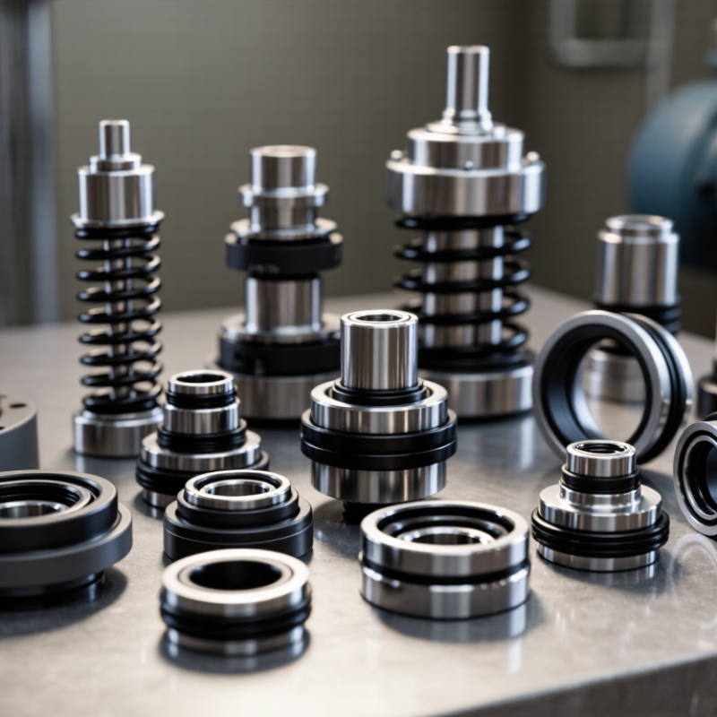
| Component-Mounted Inside Seal | Separate stationary seat, rotating seal head, spring, and elastomer installed individually inside the seal chamber. Requires accurate setting of spring length and working height. | Carbon vs. silicon carbide Carbon vs. ceramic Silicon carbide vs. silicon carbide | Nitrile rubber for general water service; EPDM for hot water and dilute chemicals; FKM for oils and many hydrocarbons. Stainless steel is common; higher-alloy metals may be selected for corrosive fluids. | Pressure: commonly up to 10 bar
Temperature: approximately -20 to 180°C, depending on elastomer and materials
Speed: commonly up to 25 m/s | General centrifugal pumps, water systems, HVAC circulation, light chemical service, and standard process duties. | Broad availability, flexible material combinations, economical replacement parts, and easy adaptation to different equipment. | Installation errors are more likely than with cartridge seals. Spring setting, face cleanliness, and axial positioning are critical. |
| Component-Mounted Outside Seal | The seal faces and spring assembly are positioned outside the pumped fluid. Often used when the fluid is corrosive and compatible external materials are easier to provide. | Carbon vs. ceramic for clean liquids; carbon vs. silicon carbide for abrasive or chemically demanding services. | EPDM, FKM, or PTFE-based secondary sealing elements according to chemical compatibility. Corrosion-resistant stainless steel or nickel-based alloys may be required. | Pressure: commonly up to 6 bar
Temperature: approximately -20 to 120°C for many elastomer arrangements
Speed: commonly up to 15 m/s | Corrosive liquids, plating solutions, wastewater chemicals, and applications where the seal metal must be protected from the process fluid. | Reduced exposure of springs and metal parts to the pumped liquid; useful for selected corrosive services. | More sensitive to pressure, shaft movement, and external damage. Not normally preferred for high-pressure or severe vacuum duty. |
| O-Ring Pusher Seal | An O-ring moves axially with the rotating seal face to compensate for wear and thermal movement. The spring package is normally located on the rotating assembly. | Carbon vs. silicon carbide for clean or abrasive liquids; carbon vs. tungsten carbide for selected industrial duties. | Nitrile rubber, EPDM, FKM, or perfluoroelastomer according to temperature and chemical exposure. Stainless steel springs are common. | Pressure: commonly up to 20 bar when properly balanced
Temperature: approximately -40 to 200°C, depending on elastomer
Speed: commonly up to 25 m/s | Pumps handling water, oils, mild chemicals, condensate, and general industrial process liquids. | Compensates for face wear, uses a familiar design, and can accommodate moderate axial movement. | O-ring hang-up can occur because of corrosion, deposits, swelling, or dry running. Not ideal for heavily crystallizing fluids. |
| Wedge Pusher Seal | A wedge-shaped secondary seal moves axially with the seal face. The design is useful where a conventional O-ring may swell or lose flexibility. | Carbon vs. silicon carbide; carbon vs. ceramic for clean water and low-abrasion service. | PTFE or filled PTFE wedge; stainless steel or corrosion-resistant alloy components. | Pressure: commonly up to 15 bar
Temperature: approximately -50 to 260°C, depending on wedge compound and hardware
Speed: commonly up to 20 m/s | Chemical processing, solvents, hydrocarbons, and fluids where elastomer compatibility is difficult. | Good chemical resistance and a wide temperature capability compared with many elastomeric pusher designs. | Requires correct installation and suitable surface finish. PTFE can creep or deform if improperly loaded or overheated. |
| Metal Bellows Seal | A welded or formed metal bellows provides spring force and secondary sealing without a dynamic O-ring on the shaft. Usually installed as a component seal. | Carbon vs. silicon carbide; silicon carbide vs. silicon carbide for abrasive, hot, or chemically aggressive service. | Formed or welded bellows in stainless steel, nickel alloy, or another compatible alloy. Static gaskets may use graphite, PTFE, or suitable elastomers. | Pressure: commonly up to 25 bar, design-dependent
Temperature: approximately -50 to 400°C with suitable materials
Speed: commonly up to 30 m/s | Hot oils, thermal fluids, solvents, high-temperature process liquids, and duties with shaft deposits. | No sliding shaft O-ring, strong high-temperature capability, and reduced risk of secondary-seal hang-up. | Higher cost and greater sensitivity to bellows fatigue, pressure reversal, vibration, and incorrect face loading. |
| Rubber Bellows Seal | A molded elastomer bellows flexes to provide axial movement and secondary sealing. It is normally a simple, non-cartridge component arrangement. | Carbon vs. ceramic for clean water; carbon vs. silicon carbide where improved wear resistance is needed. | Nitrile rubber, EPDM, or FKM bellows; stainless steel hardware is common. | Pressure: commonly up to 8 bar
Temperature: approximately -40 to 150°C, depending on elastomer
Speed: commonly up to 15 m/s | Water pumps, swimming pools, household equipment, agricultural systems, and low-to-moderate duty circulation. | Simple design, good tolerance for minor shaft movement, and no dynamic O-ring sliding on the shaft. | Limited resistance to high temperature, oil swelling, ozone, and aggressive chemicals. Bellows must not be overstretched. |
| Balanced Component Seal | The hydraulic area acting on the seal face is reduced by the balance design. It may use an O-ring, wedge, or bellows secondary seal and is installed piece by piece. | Carbon vs. silicon carbide or tungsten carbide for higher pressure and wear resistance. | Secondary seal selected for the fluid; stainless steel or higher-alloy springs and retainers may be used. | Pressure: commonly 20 to 40 bar, subject to speed and face design
Temperature: approximately -40 to 250°C
Speed: commonly up to 30 m/s | High-pressure pumps, boiler-feed auxiliaries, hydrocarbon service, and process equipment with substantial pressure loading. | Lower face loading and heat generation than a comparable unbalanced seal; better suitability for higher pressure. | More complex dimensions and installation requirements. Balance ratio, pressure direction, and face stability must be checked. |
| Unbalanced Component Seal | A simpler component seal in which a larger hydraulic area loads the seal faces. Common for low- and medium-pressure equipment. | Carbon vs. ceramic or silicon carbide for general service; harder faces are preferred for abrasives. | Nitrile rubber, EPDM, FKM, or PTFE-based secondary seals; stainless steel hardware for ordinary environments. | Pressure: commonly up to 10 to 15 bar
Temperature: approximately -20 to 180°C, material-dependent
Speed: commonly up to 20 m/s | Water, clean liquids, low-pressure chemical service, and cost-sensitive replacement applications. | Simple construction, low initial cost, and straightforward maintenance for standard pump duties. | Higher face loading can increase heat, wear, and power loss at elevated pressure or speed. |
| Split Mechanical Seal | Rotating and stationary components are divided into sections so the seal can be installed without removing the shaft, coupling, or large equipment. | Carbon vs. silicon carbide for water and process liquids; hard-face combinations are preferred for solids or poor lubrication. | Elastomer or graphite secondary seals; stainless steel and corrosion-resistant alloy hardware are commonly used. | Pressure: commonly up to 30 bar, application-dependent
Temperature: approximately -40 to 180°C for many arrangements
Speed: commonly up to 20 m/s | Large pumps, cooling-water systems, power plants, marine equipment, and equipment where dismantling is costly. | Faster installation on large or difficult-to-access equipment and reduced downtime during replacement. | Higher purchase price and more demanding assembly. Split-face alignment, cleanliness, and bolt tightening are critical. |
| Double Non-Cartridge Seal Arrangement | Two component seals are installed in tandem or face-to-face configuration with a barrier or buffer fluid between them. External support equipment is normally required. | Silicon carbide vs. silicon carbide or carbon vs. silicon carbide, selected according to lubrication and chemical conditions. | Secondary seals must be compatible with both the process fluid and barrier fluid. Metal parts require corrosion resistance for the external system. | Process pressure: commonly up to 25 bar
Temperature: approximately -40 to 200°C, design-dependent
Speed: commonly up to 25 m/s | Toxic, flammable, crystallizing, abrasive, or environmentally sensitive fluids where leakage containment is important. | Provides controlled leakage management, improved lubrication, and protection against dry running when the support system is correctly operated. | Higher installation complexity, additional piping or monitoring, and ongoing barrier-fluid management requirements. |