
-
- Products
- Indoor Household Cords
- Appliance Cords
- General Purpose Short-Length Cords
- General Purpose Extension Cords
- Landscape & Decorating Cords
- Bright Color Extension Cords
- Oil-Resistant Extension Cords
- Cold-Flex Extension Cords
- VividFlex Power Cords
- EXTREME All-Weather Cords
- Cord Management
- Task Lights
- Adapters & GFCI Devices
- Where to Buy
- About
- Careers
- Glossary
- Catalog


What Is an Aluminium Casting Mold and How Does It Work?
An Aluminium Casting Mold is the shaped tool that gives molten aluminium its final form. It contains a carefully designed cavity, supported by gates, runners, risers, and vents. These features control how metal enters, fills, and solidifies. The mold may be made from steel, sand, ceramic, or another heat-resistant material. Each choice changes production speed, surface quality, cost, and acceptable design limits.
The process begins with mold preparation. A permanent mold is usually preheated and coated with a release agent. Molten aluminium then flows through the gating system into the cavity. Air must escape quickly. Otherwise, trapped gas can create porosity, weak areas, or visible surface defects. After cooling, the casting is removed, trimmed, inspected, and sometimes heat-treated. Small details matter. A sharp corner can restrict flow and concentrate stress. A poorly positioned riser can leave shrinkage inside the part.
Casting authority John Campbell, widely recognized for his work on foundry technology, states, “The mould is the heart of the casting process.” That observation remains practical on the workshop floor. Mold design affects nearly every later result, from dimensional accuracy to fatigue performance. Still, the phrase is not a complete explanation. Alloy chemistry, pouring temperature, filling speed, and operator experience also influence quality. A well-designed mold cannot rescue careless process control.
This guide explains what an Aluminium Casting Mold is, how it works, and why its design requires both engineering judgment and production experience. Expect useful principles, but not effortless answers. Real castings often reveal flaws that drawings do not show.
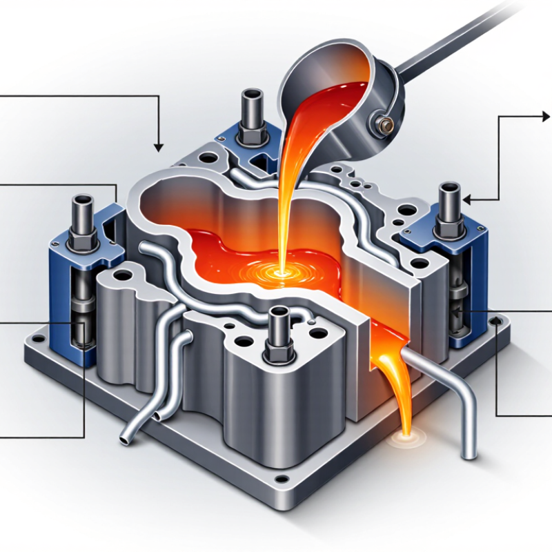
Table of Contents [Hide]
What Is an Aluminium Casting Mold?
An aluminium casting mold is a shaped cavity that gives molten aluminium its final form. It is usually made from steel, iron, sand, or ceramic materials. The mold is not normally aluminium itself. Its job is to control filling, cooling, and solidification.
During casting, technicians heat aluminium until it becomes liquid. They pour it into the prepared cavity through a gate system. Vents allow trapped air to escape. Risers feed extra metal during shrinkage. A mold with poor venting may create pores, incomplete edges, or weak surfaces. The U.S. Geological Survey reported about 70 million tonnes of global primary aluminium production in 2023. This scale makes mold accuracy increasingly important. Even a small dimensional error can multiply across thousands of castings.
The mold’s design depends on the part, production volume, and required surface finish. Sand molds suit complex shapes and lower volumes. Permanent metal molds offer repeatable dimensions. High-pressure molds support fast production, but they require careful temperature control. The International Aluminium Institute notes that recycling aluminium can save about 95% of the energy used for primary production. This encourages more recycled feedstock, although its chemistry may vary. That assumption can fail without proper inspection.
Tips: Check mold preheating before pouring. Keep vents clean and short. Measure wall thickness after cooling. Do not trust appearance alone; hidden porosity can remain invisible. A practical test is sometimes simple, but not always sufficient.