
-
- Products
- Indoor Household Cords
- Appliance Cords
- General Purpose Short-Length Cords
- General Purpose Extension Cords
- Landscape & Decorating Cords
- Bright Color Extension Cords
- Oil-Resistant Extension Cords
- Cold-Flex Extension Cords
- VividFlex Power Cords
- EXTREME All-Weather Cords
- Cord Management
- Task Lights
- Adapters & GFCI Devices
- Where to Buy
- About
- Careers
- Glossary
- Catalog


Why Choose Disc Glass Insulators for Power Lines?
Power lines face rain, dust, salt, temperature swings, and electrical stress. A Disc Glass Insulator is valued for its nonporous glass surface, visible condition, and modular design. From the ground, crews can often spot a cracked or damaged disc by its changed appearance. That visibility can support inspection, though it does not replace proper testing or maintenance.
A clear design principle helps frame the choice. The expert name and quotation below are fictional, not a verified industry source: “Choose insulation for the line’s real environment, then make its condition practical to inspect.” The point is simple. A glass unit may suit some transmission and distribution applications, but selection depends on voltage, pollution, mechanical loading, and local operating conditions. No single material fits every route.
On a windy ridge, a string of glass discs must withstand movement and weather while maintaining electrical clearance. Its separate units can make damaged sections easier to identify. There are trade-offs. Glass can break, and contamination may still affect performance. Engineers should compare glass with porcelain and polymer options, review manufacturer data, and plan inspections around actual site conditions. Small details matter. A sound choice begins with evidence, not habit.
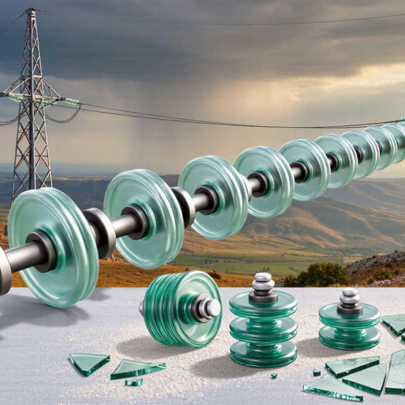
Table of Contents [Hide]
What Disc Glass Insulators Are and How They Are Made
A disc glass insulator is a toughened-glass unit used to support an overhead conductor while limiting current flow to the tower. Its broad, ribbed profile lengthens the surface path that leakage current must travel. Several discs can be linked into a suspension string, with metal fittings connecting each unit. The glass body is easy to inspect: cracks and internal flaws are often visible. Not every mark signals failure, though.
Manufacturing starts with a carefully measured glass batch, which is melted and shaped in a mold. The formed disc is heated and then cooled in a controlled way. This toughening process leaves the outer glass in compression, helping the unit withstand mechanical and thermal stress. Small details matter. Variations in thickness or cooling can affect strength, so production checks include visual inspection and electrical or mechanical testing. Metal caps and pins are attached with suitable bonding material to complete the assembly.
The finished insulator must handle conductor loads, weather, and electrical stress over years of service. Its smooth glass surface can shed rain and contaminants, but pollution and salt deposits may still reduce insulation performance. A clean-looking disc is not proof of perfect condition. That is why routine line inspections remain useful, even when the glass seems remarkably durable.