
-
- Products
- Indoor Household Cords
- Appliance Cords
- General Purpose Short-Length Cords
- General Purpose Extension Cords
- Landscape & Decorating Cords
- Bright Color Extension Cords
- Oil-Resistant Extension Cords
- Cold-Flex Extension Cords
- VividFlex Power Cords
- EXTREME All-Weather Cords
- Cord Management
- Task Lights
- Adapters & GFCI Devices
- Where to Buy
- About
- Careers
- Glossary
- Catalog


10 Best Electrical Test Kits for Professionals
Choosing an Electrical Test Kit is not simply a matter of counting tools. A professional needs instruments suited to the work, the environment, and the readings required. On a service call, that may mean checking voltage at a panel, tracing a circuit, or confirming continuity at a small terminal. The right kit makes these checks more efficient. It does not replace training or careful judgment.
Electrical safety educator Jim Phillips has emphasized the importance of safe work practices and training. The following line is an editorial summary of that principle, not a verbatim quotation: “A reading is only trustworthy when the instrument, leads, setup, and user are ready.” It is worth remembering. A damaged probe or incorrect meter setting can undermine an otherwise careful measurement. Specifications matter, but so do clear displays, durable cases, and leads that are easy to inspect.
This guide compares ten test kits for working professionals, including options for common electrical troubleshooting and more demanding measurement tasks. It considers measurement range, included accessories, portability, and practical ease of use. Some kits offer impressive breadth; others keep the essentials close at hand. Neither approach suits every technician. A kit that looks complete on paper may still feel awkward beside a crowded panel. Use these comparisons as a starting point, then check each instrument’s ratings and instructions against the work you actually perform. A little doubt is useful. It keeps the choice grounded in the job, not just the product description.
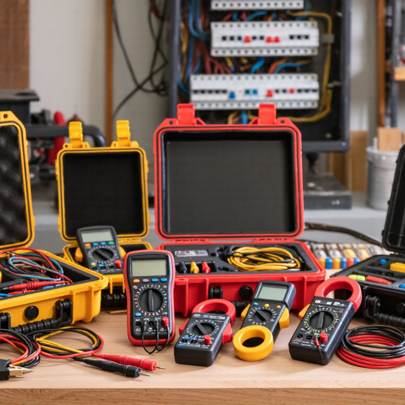
Table of Contents [Hide]
What Electrical Test Kits Are and How Professionals Use Them
An electrical test kit groups tools used to check voltage, current, continuity, and insulation. A typical kit may include a digital multimeter, clamp meter, voltage detector, and insulated probes. Each tool answers a different question: Is a circuit energized? Is a conductor carrying current? Is a connection open? For example, a technician might check a panel, then clamp around one conductor to measure current without disconnecting it. The right tool depends on the task and its measurement category. A high voltage rating alone does not establish suitability for every installation.
The U.S. Bureau of Labor Statistics reported 145 fatal work injuries involving exposure to electricity in its 2022 Census of Fatal Occupational Injuries. That figure is a reminder, not proof that test kits alone prevent harm. Professionals inspect leads, select equipment with an appropriate measurement category, and verify a tester on a known source before and after checking a circuit. Small steps matter. Still, a meter can give false confidence if used incorrectly. Readings need context: unexpected values may reflect a poor connection, an unsuitable setting, or a real fault. Even experienced workers should pause and reassess when a result does not fit the equipment or the job.