
-
- Products
- Indoor Household Cords
- Appliance Cords
- General Purpose Short-Length Cords
- General Purpose Extension Cords
- Landscape & Decorating Cords
- Bright Color Extension Cords
- Oil-Resistant Extension Cords
- Cold-Flex Extension Cords
- VividFlex Power Cords
- EXTREME All-Weather Cords
- Cord Management
- Task Lights
- Adapters & GFCI Devices
- Where to Buy
- About
- Careers
- Glossary
- Catalog


What Is a Brushless Motor and How Does It Work?
A brushless motor can look almost ordinary from the outside: a compact metal case, a shaft, and wires leading to an electronic controller. Inside, permanent magnets rotate around or within windings, while the controller switches current through those windings in a timed sequence. There are no brushes rubbing against a commutator. Less friction. Less routine wear.
Austin Hughes, co-author of Electric Motors and Drives, explains motor-drive principles that include electronic commutation. A concise paraphrase of the key idea is: “Electronic switching replaces the mechanical commutation performed by brushes.” This is a paraphrase, not a direct quotation. It points to the defining difference—and to why controller design matters as much as the motor itself.
Understanding how a brushless motor works means following the sequence: a sensor or controller estimates rotor position, current energizes selected coils, and magnetic forces turn the shaft. The process repeats rapidly. In a small drone, that sequence helps deliver quick changes in speed; in a workshop fan, it can support quiet, steady rotation. Performance still depends on the motor, controller, load, and cooling working together. A high efficiency figure alone tells only part of the story. The details can be less tidy than a simple diagram suggests, especially when sensorless control must infer rotor position at low speeds. This guide explains the main parts, the switching process, and the practical trade-offs behind the technology.
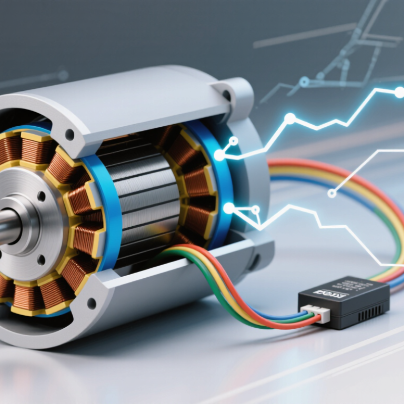
Table of Contents [Hide]
What Defines a Brushless Motor?
A brushless motor has no carbon brushes rubbing against a commutator to deliver current to its rotating part. That missing contact is its defining feature. Coils sit in the stationary section, called the stator, while permanent magnets are commonly attached to the rotor. The controller switches current through the coils in a timed sequence, creating a magnetic field that pulls the rotor around. That is the basic idea.
The timing matters. Sensors may report the rotor’s position, or the controller may estimate it from electrical signals. With that information, it energizes the right coils as the rotor turns. Picture a small fan starting quietly on a desk: its controller adjusts the magnetic push rather than relying on sliding contacts. The exact design varies, so not every brushless motor starts or responds in the same way.
Removing brushes reduces friction and wear at that contact point, and it avoids brush-generated electrical sparking. It does not make the motor maintenance-free. Bearings can still wear, and heat can damage insulation or magnets. The electronic controller also adds complexity and needs suitable settings. “Brushless” sounds like a complete description, but it leaves out important details, including motor construction, cooling, and control quality.