
-
- Products
- Indoor Household Cords
- Appliance Cords
- General Purpose Short-Length Cords
- General Purpose Extension Cords
- Landscape & Decorating Cords
- Bright Color Extension Cords
- Oil-Resistant Extension Cords
- Cold-Flex Extension Cords
- VividFlex Power Cords
- EXTREME All-Weather Cords
- Cord Management
- Task Lights
- Adapters & GFCI Devices
- Where to Buy
- About
- Careers
- Glossary
- Catalog


How to Choose Power Resistors for Global Sourcing?
How to Choose Power Resistors for Global Sourcing?
Selecting Power Resistors for global sourcing is not simply a matter of comparing prices. A resistor that survives a 200°C cabinet may fail quickly in a compact inverter. The correct choice depends on resistance value, rated power, pulse energy, tolerance, temperature coefficient, and mounting conditions. Felix Zandman, founder of Vishay Intertechnology, expressed a relevant engineering principle: “The most important thing is not the idea, but its execution.” That principle applies directly to resistor sourcing. A datasheet may look impressive, yet production results can differ.
Begin with the application environment. Check continuous load, overload duration, airflow, vibration, humidity, and expected service life. Apply derating instead of using the nominal wattage at its limit. A 100-watt resistor may need to operate closer to 60 or 70 watts in a warm enclosure. Small details matter. Terminal strength matters. Coating quality matters.
Global suppliers should provide consistent samples, traceable materials, inspection records, and stable production capacity. Ask for test data, not only certificates. Verify RoHS, REACH, and customer-specific requirements through current documentation. For automotive or industrial projects, review relevant qualification standards carefully. Factory audits can reveal weak winding control, uneven coatings, or poor packaging. These defects may remain invisible during a basic sample test.
No sourcing plan is perfect. Forecasts change. A cheaper component may create higher cooling costs or unexpected field failures. Compare total ownership cost, lead time, logistics risk, and technical support. The strongest decision balances electrical performance with dependable supply. That balance takes careful review, and sometimes a second look.
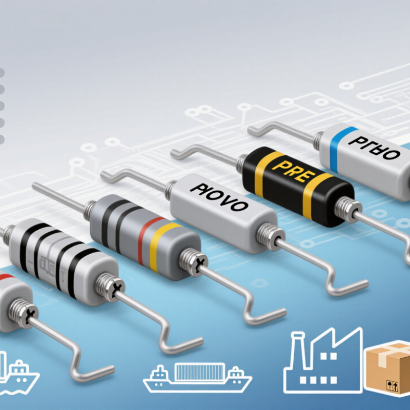
Table of Contents [Hide]
Define Power Resistor Types, Ratings, and Key Performance Parameters
How to Choose Power Resistors for Global Sourcing?
Power resistor selection starts with type, not price. Wirewound resistors handle high energy and pulse loads, but their inductance can disturb fast switching. Thick-film and metal-oxide types offer compact layouts and strong overload performance. Aluminum-housed resistors suit chassis mounting and continuous heat dissipation.
Check four ratings together: resistance, power, voltage, and pulse energy. Rated power assumes a specific ambient temperature and mounting condition. Apply derating when airflow is limited. A practical rule is operating below 70% of rated power. Calculate heat with P = I²R or P = V²/R. Then inspect thermal resistance, tolerance, temperature coefficient, and insulation voltage. IEC 60115-1 provides general reliability and test requirements for fixed resistors. It should support, not replace, application testing.
Demand is moving toward higher electrical loads. The International Energy Agency reported over 17 million electric cars sold globally in 2024. This growth increases pressure on braking, charging, and protection circuits. Pulse capability matters here. A resistor surviving 100 watts for one second may fail under repeated 20-watt pulses. Ask suppliers for pulse graphs, derating curves, sample inspection data, and change-control procedures. Global sourcing also requires clear units and test conditions.
I have seen teams compare wattage only. That shortcut fails. Specifications can look complete while omitting mounting temperature. Recheck the assumptions. A slightly larger resistor may deliver better thermal stability, easier inspection, and fewer field surprises. Sources: IEC 60115-1; International Energy Agency, Global EV Outlook 2025.
How to Choose Power Resistors for Global Sourcing? - Define Power Resistor Types, Ratings, and Key Performance Parameters
| Power Resistor Type | Construction and Operating Principle | Typical Rated Power | Typical Resistance Range | Typical Tolerance | Typical TCR | Key Strengths | Main Limitations | Common Applications |
|---|---|---|---|---|---|---|---|---|
| Wirewound Power Resistor | Resistance wire wound on a ceramic or insulating core and protected with a coating, case, or housing. | 2 W to 500 W; higher assemblies are possible with suitable cooling. | Approximately 0.01 Ω to 100 kΩ. | ±0.5% to ±10%. | Approximately ±20 to ±400 ppm/°C, depending on alloy and construction. | High power capability, strong overload performance, and good long-term stability. | Inductance may be significant; high-frequency performance can be limited. | Power supplies, motor controls, load banks, braking circuits, and pulse-damping networks. |
| Thick-Film Power Resistor | A resistive paste is printed or deposited on a ceramic substrate and then fired to form the resistive element. | 0.25 W to 100 W for common surface-mount and leaded formats. | Approximately 0.01 Ω to 10 MΩ. | ±1% to ±10%. | Approximately ±100 to ±600 ppm/°C. | Compact size, economical production, and broad availability in surface-mount packages. | Resistance and power capability can change significantly with temperature and mounting conditions. | Power management boards, LED drivers, consumer electronics, and industrial control equipment. |
| Thin-Film Power Resistor | A thin resistive film is formed on a ceramic substrate, typically by vacuum deposition or a similar controlled process. | 0.1 W to 10 W in standard power packages. | Approximately 1 Ω to 1 MΩ. | ±0.05% to ±1%. | Approximately ±5 to ±100 ppm/°C. | Low noise, tight tolerance, low TCR, and good matching performance. | Usually more expensive and less suitable for very high energy or extreme overload conditions. | Precision measurement, feedback networks, instrumentation, and control circuits. |
| Metal Oxide Film Resistor | A metal-oxide resistive layer is formed on a ceramic core and protected with an insulating coating. | 0.5 W to 10 W for common leaded designs. | Approximately 1 Ω to 1 MΩ. | ±1% to ±5%. | Approximately ±50 to ±350 ppm/°C. | Good thermal stability, reasonable surge capability, and higher temperature endurance than many general-purpose film types. | Not normally the first choice for very low resistance or very high precision. | Power supply input circuits, general industrial electronics, and high-voltage bias networks. |
| Metal Element Shunt Resistor | A low-resistance metal alloy element is designed to produce a measurable voltage drop proportional to current. | 0.5 W to 100 W or more, depending on package and cooling. | Approximately 0.0005 Ω to 0.5 Ω. | ±0.5% to ±5%. | Approximately ±15 to ±100 ppm/°C. | Low resistance, low inductance options, and accurate current measurement. | Self-heating, PCB copper layout, solder joints, and Kelvin connections can strongly affect accuracy. | Battery management, current sensing, motor drives, power converters, and protection circuits. |
| Aluminum-Housed Power Resistor | A wirewound or film element is enclosed in an aluminum case that transfers heat to a chassis or heatsink. | 10 W to 1,000 W, with the actual rating dependent on case temperature and mounting. | Approximately 0.01 Ω to 100 kΩ. | ±1% to ±10%. | Approximately ±20 to ±400 ppm/°C. | Efficient heat transfer, rugged mounting, and suitability for continuous high-power dissipation. | Requires mechanical mounting; rated power must be derated if heat removal is inadequate. | Industrial drives, automation systems, power supplies, braking units, and test equipment. |
| Cement or Ceramic-Cased Resistor | A resistive element is enclosed in cement or ceramic material to provide electrical insulation and mechanical protection. | 2 W to 100 W in common leaded formats. | Approximately 0.1 Ω to 100 kΩ. | ±2% to ±10%. | Approximately ±100 to ±500 ppm/°C. | Low cost, good insulation, robust construction, and reasonable pulse tolerance. | Large physical size, relatively high surface temperature, and moderate precision. | Power supply bleeder circuits, snubbers, appliance controls, and general industrial equipment. |
| Dynamic Braking or Grid Resistor | A high-power resistance element, often an alloy grid or tubular assembly, converts electrical energy into heat during braking or load testing. | Hundreds of watts to hundreds of kilowatts in modular assemblies. | Typically below 1 Ω to several hundred Ω. | Commonly ±5% to ±10%. | Often specified by resistance alloy and operating temperature rather than precision TCR. | Handles high energy, repeated overloads, and short-duration regenerative braking events. | Requires airflow, guarding, thermal protection, and careful consideration of duty cycle. | Elevator drives, cranes, conveyors, rail equipment, motor test systems, and load banks. |
Key Performance Parameters for Global Sourcing
| Parameter | Definition | Why It Matters When Sourcing | Recommended Specification Practice |
|---|---|---|---|
| Rated Power | The maximum continuous power the resistor can dissipate under specified ambient, case, or heatsink conditions. | The same nominal wattage may produce different results because cooling, mounting, and ambient temperature vary. | Specify the required derating curve, mounting method, ambient temperature, and duty cycle. |
| Resistance Value | The nominal electrical resistance measured under defined test conditions. | Determines current, voltage drop, heat generation, and circuit operating point. | Define the nominal value, tolerance, measurement temperature, and acceptable drift after aging. |
| Tolerance | The permitted initial deviation from the nominal resistance value. | Affects current sharing, sensing accuracy, feedback stability, and production yield. | Use the narrowest tolerance that the circuit genuinely requires to control cost and supply risk. |
| Temperature Coefficient of Resistance | The change in resistance with temperature, normally expressed in ppm/°C. | Self-heating and ambient changes can alter resistance during operation. | Specify the TCR range and temperature interval, not only a typical value. |
| Working Voltage | The maximum continuous voltage permitted across the resistor, limited by construction and insulation. | A resistor can exceed its power limit or voltage limit first, especially at high resistance values. | Check both V = √(P × R) and the manufacturer-stated working-voltage limit. |
| Overload and Pulse Capability | The ability to withstand a temporary power or energy pulse without unacceptable damage or resistance shift. | Startup surges, capacitor discharge, inrush current, and braking events may exceed continuous ratings. | Specify pulse duration, peak power, energy in joules, repetition rate, and required post-pulse drift. |
| Thermal Derating | The reduction in allowable power as ambient, case, or mounting temperature increases. | Prevents overheating, accelerated aging, solder damage, and premature failure. | Request the derating curve and define the maximum allowable surface or case temperature. |
| Reliability and Environmental Rating | The resistor's ability to maintain performance under humidity, vibration, temperature cycling, and long-term operation. | Global applications may involve different climates, transportation conditions, and regulatory requirements. | Define operating temperature, humidity, vibration, flammability, insulation, and qualification-test requirements. |
| Package and Mounting | The physical form, terminal arrangement, footprint, clearance, and heat-transfer path. | Incorrect mounting can reduce power capability and create assembly or safety problems. | Confirm dimensions, terminal material, torque requirements, creepage, clearance, and PCB copper area. |
| Compliance and Documentation | Evidence that the part meets applicable material, safety, quality, and traceability requirements. | Documentation reduces qualification delays and supports customs, audits, and product safety reviews. | Request controlled drawings, test reports, material declarations, lot traceability, and change-notification procedures. |
Note: The numerical ranges shown are typical industry ranges for comparison only. Actual limits depend on resistor construction, package size, test method, mounting arrangement, cooling conditions, and the applicable product datasheet.