
-
- Products
- Indoor Household Cords
- Appliance Cords
- General Purpose Short-Length Cords
- General Purpose Extension Cords
- Landscape & Decorating Cords
- Bright Color Extension Cords
- Oil-Resistant Extension Cords
- Cold-Flex Extension Cords
- VividFlex Power Cords
- EXTREME All-Weather Cords
- Cord Management
- Task Lights
- Adapters & GFCI Devices
- Where to Buy
- About
- Careers
- Glossary
- Catalog


How to Choose the Right BMS PCB for Your Product?
Choosing the right Battery Management System PCB (BMS PCB) can determine whether a battery product performs reliably in real operating conditions. The board must monitor cell voltage, temperature, current, and charging status with consistent accuracy. A small measurement error can reduce usable capacity or create an unsafe charging decision. Designers should examine the battery chemistry, cell count, peak current, communication interface, and expected operating temperature before selecting a circuit.
A compact lithium-ion pack may need a six-cell BMS PCB with balancing control, several thermistor inputs, and CAN communication. A high-current industrial module may require wider copper paths, stronger MOSFETs, isolated communications, and improved heat dissipation. Look closely at the shunt resistor, connector ratings, creepage distances, and protection thresholds. These details often matter more than a long feature list. They also affect enclosure size, wiring complexity, production cost, and service access.
A reliable selection process combines manufacturer documentation, test data, and application-specific validation. Check whether the design supports relevant safety and performance expectations, such as IEC 62133 or UL 1973, where applicable. Certification alone is not a complete guarantee. A certified board can still be poorly matched to your cells, charger, or firmware strategy. That is an easy mistake to make. Engineers should test abnormal temperatures, sudden load changes, communication loss, and repeated charge cycles. In practical design reviews, teams sometimes focus on maximum current and overlook balancing speed. That oversight can appear only after months of field use. The best choice balances protection, measurement accuracy, integration effort, maintainability, and realistic production requirements. It may not be the cheapest option, but it should be explainable, testable, and dependable.
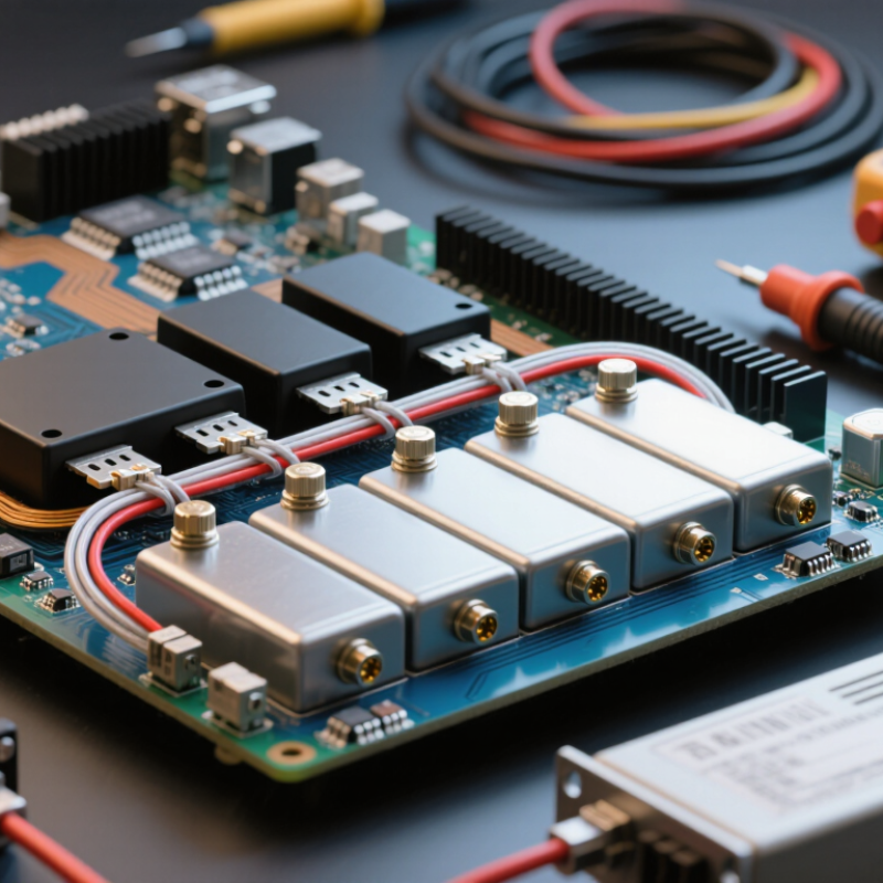
Table of Contents [Hide]
Define the Role of a BMS PCB in Your Product
A BMS PCB is the product’s electrical control center. It measures cell voltage, pack current, and temperature. It also controls balancing, charging, discharge, communication, and emergency shutdown. The PCB connects battery cells with the charger, motor, or device load. Its role depends on the product, not only the battery size. The International Energy Agency reported that electric vehicle battery demand exceeded 750 GWh in 2023. This growth increases pressure on accurate sensing and reliable protection.
When choosing a BMS PCB, define the battery architecture first. Record the cell chemistry, series count, peak current, operating temperature, and expected service life. A compact medical device may need low noise and careful temperature monitoring. An industrial pack may require stronger switching components and communication diagnostics. Designers sometimes choose a higher current rating and stop there. That can be misleading. Thermal paths, connector limits, balancing speed, and software response also shape real performance. I have seen prototypes pass basic tests but fail during repeated high-load cycles. The PCB must match the complete operating profile.
Tips: Leave measurement margins for voltage and temperature. Check balancing performance at low charge levels. Review creepage, clearance, EMC, and fault-handling requirements early. Ask for test evidence, not only a specification sheet. A useful design review includes abnormal conditions, because normal operation rarely reveals every weakness. Reconsider the choice after thermal testing.