
-
- Products
- Indoor Household Cords
- Appliance Cords
- General Purpose Short-Length Cords
- General Purpose Extension Cords
- Landscape & Decorating Cords
- Bright Color Extension Cords
- Oil-Resistant Extension Cords
- Cold-Flex Extension Cords
- VividFlex Power Cords
- EXTREME All-Weather Cords
- Cord Management
- Task Lights
- Adapters & GFCI Devices
- Where to Buy
- About
- Careers
- Glossary
- Catalog


How to Choose the Right ELCB Circuit Breaker?
Choosing the right Elcb Circuit Breaker is not simply a matter of selecting the highest current rating. It requires a careful match between electrical load, leakage protection, installation conditions, and expected human contact. An unsuitable device may trip too often, or fail to respond when protection matters most.
Electrical safety consultant John Cadick offers a useful warning: “A protective device cannot compensate for poor design, installation, or maintenance.” This principle applies directly to ELCB selection. Check the circuit voltage, rated current, breaking capacity, and number of poles. Then examine the required residual-current sensitivity, such as 30 mA for additional personal protection where applicable. A 100 mA or 300 mA device may suit fire protection or equipment protection, but it may not provide the same personal protection.
Small details matter.
Consider whether the circuit supplies lighting, heating, motors, computers, or variable-speed equipment. Some loads create pulsating or smooth residual currents, making Type AC unsuitable in certain applications. Type A or more advanced protection may be necessary, depending on the equipment and local standards. Moisture, dust, outdoor exposure, and poor earthing also influence the decision.
Do not trust the label alone. Verify certification, manufacturer instructions, test-button operation, and compatibility with the distribution board. A monthly test may reveal a problem, although the exact schedule should follow local guidance. I have to admit that selection tables can look more certain than real installations. A qualified electrician should confirm the final choice, because the best Elcb Circuit Breaker is the one that works correctly within the entire protection system.
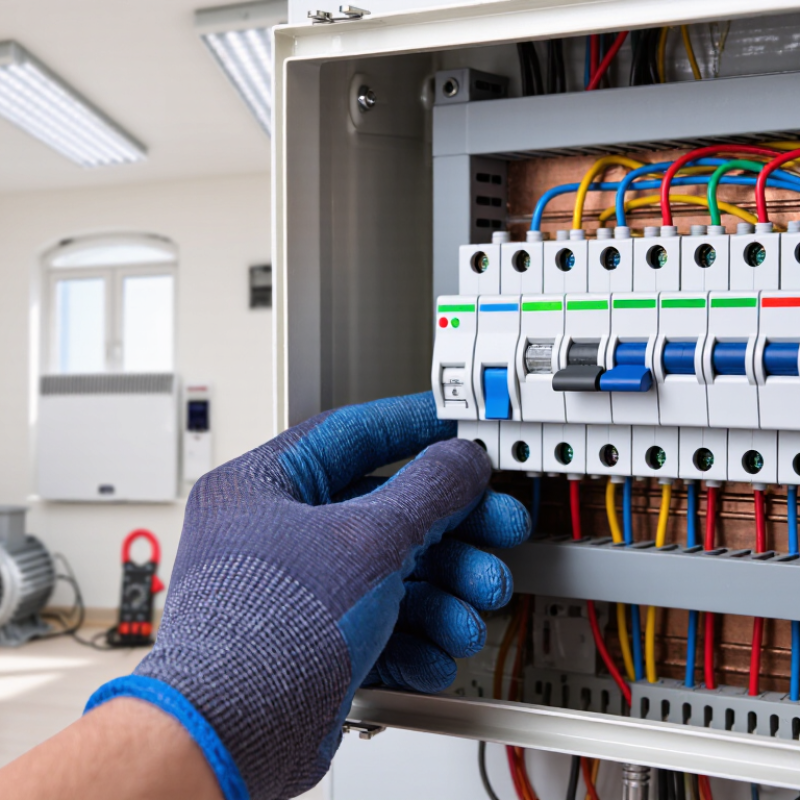
Table of Contents [Hide]
Define ELCB Types: Voltage-Operated ELCB vs IEC 61008-1 RCCB
How to Choose the Right ELCB Circuit Breaker?
Voltage-operated ELCBs and IEC 61008-1 RCCBs detect different electrical hazards. A voltage-operated ELCB monitors the voltage between exposed metalwork and earth. It trips when leakage raises that voltage beyond its setting. This design depends heavily on the earth electrode, protective conductor, and installation condition. Poor earthing can reduce its protection.
An IEC 61008-1 RCCB compares current in the live and neutral conductors. It disconnects the circuit when their currents differ, indicating leakage through equipment or a person. It does not provide overcurrent protection, so a suitable circuit breaker remains necessary. In practice, I check rated residual operating current, breaking coordination, test-button operation, and neutral routing. A common mistake is assuming every RCCB prevents every shock. It does not.
NFPA’s Home Fires Involving Electrical Distribution and Lighting Equipment report recorded an annual average of 32,620 U.S. home fires from 2015–2019. These fires caused about 470 civilian deaths and 1,100 injuries each year.
Tips
Prefer an IEC 61008-1 RCCB for modern installations where residual-current sensing is required. Confirm compatibility with the earthing system. Test the device regularly. Record the result. A qualified electrician should verify disconnection time and coordination, because site conditions can expose weaknesses that product labels cannot show.