
-
- Products
- Indoor Household Cords
- Appliance Cords
- General Purpose Short-Length Cords
- General Purpose Extension Cords
- Landscape & Decorating Cords
- Bright Color Extension Cords
- Oil-Resistant Extension Cords
- Cold-Flex Extension Cords
- VividFlex Power Cords
- EXTREME All-Weather Cords
- Cord Management
- Task Lights
- Adapters & GFCI Devices
- Where to Buy
- About
- Careers
- Glossary
- Catalog


How to Choose the Right Electric Furnace Transformer?
Choosing the right Electric Furnace Transformer is a practical engineering decision, not a simple equipment purchase. It affects furnace stability, production quality, energy use, and long-term maintenance costs. A transformer may look suitable on paper, yet perform poorly under repeated thermal cycling or sudden load changes.
This guide explains the main factors professionals review before approving a transformer. These include furnace capacity, primary and secondary voltage, frequency, impedance, phase arrangement, cooling method, and expected duty cycle. Harmonic distortion also deserves attention, especially in installations using thyristor controls or other power-electronic equipment. A transformer room may appear quiet during inspection, while temperature rise tells a different story after several hours of operation.
Site conditions matter. Dust, heat, vibration, limited ventilation, and restricted maintenance access can change the correct specification. Experienced engineers compare manufacturer data with measured operating conditions, rather than relying on nominal ratings alone. They also verify efficiency, insulation class, protection systems, noise levels, and compliance with applicable electrical standards.
No selection method is perfect. Unexpected production changes can expose weaknesses that calculations missed. That is why load records, fault studies, factory test reports, and supplier references should support the final decision. Small details matter. A loose connection, insufficient cooling clearance, or unsuitable tap range can create expensive downtime.
The best transformer balances reliability, performance, safety, and total ownership cost. It should serve the furnace today and remain adaptable tomorrow. This article offers a clear framework for making that choice with greater confidence and fewer costly assumptions.
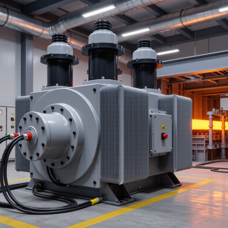
Table of Contents [Hide]
Understanding the Role and Types of Electric Furnace Transformers
How to Choose the Right Electric Furnace Transformer?
An electric furnace transformer converts incoming voltage into the lower voltage and higher current required by the furnace. Its role is not simply to supply power. It must also handle frequent starts, thermal stress, voltage fluctuations, and sudden load changes. That matters.
Arc furnace transformers serve melting systems that draw intense, unstable current through electrodes. They usually require strong short-circuit performance, robust cooling, and adjustable voltage control. Induction furnace transformers support coil-based heating, where stable output and high current help maintain efficient electromagnetic heating. Resistance furnace transformers are often selected for steadier heating loads, but their insulation and temperature ratings still need careful review.
Common construction choices include oil-immersed and dry-type transformers. Oil-immersed units can manage heavy loads and outdoor conditions effectively when maintenance is properly controlled. Dry-type units may suit indoor installations where fire protection and cleaner operation are priorities. The correct choice depends on furnace capacity, duty cycle, voltage range, installation space, and local safety requirements.
Engineers should examine harmonics, inrush current, cooling capacity, impedance, and tap-changer performance before approving a design. A transformer that matches the furnace’s rated power may still perform poorly during peak cycles. Field measurements are valuable, especially when the furnace operates near its limits. The calculation is rarely perfect. Ambient temperature, cable length, and future production changes can alter the result. Reliable selection combines manufacturer data, site conditions, protection studies, and practical operating records.