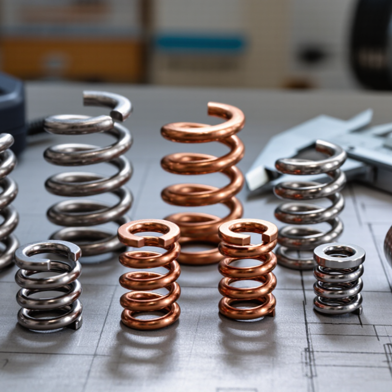
| Material and Electrical Conductivity | Select a material that provides the required current capacity, spring force, and corrosion resistance. | Phosphor bronze, beryllium copper, austenitic stainless spring steel, nickel-based spring alloys. | Approximate conductivity: phosphor bronze 13–18% IACS; beryllium copper 20–60% IACS depending on temper; 301 stainless steel about 2–3% IACS. | Four-wire resistance measurement and material certificate review. | Use copper alloys for lower resistance. Use stainless spring steel where high strength, low magnetic permeability, or improved oxidation resistance is more important than conductivity. |
| Dimensional Accuracy | Define tolerances for overall length, contact height, slot width, hole position, and formed angle. | All stamped spring materials; accuracy depends mainly on tooling, material thickness, and forming control. | A practical starting point for fine stamped parts is ±0.05–0.15 mm for critical dimensions, subject to thickness, geometry, and tool capability. | Coordinate-measuring machine, optical measurement, pin gauges, and go/no-go fixtures. | Use tighter tolerances only where they affect contact alignment, insertion force, electrical travel, or assembly clearance. |
| Material Thickness Control | Control thickness variation to maintain consistent spring force and formed geometry. | Copper alloys and stainless spring steels supplied in precision strip form. | Typical thin-strip contact springs use approximately 0.10–0.80 mm material, depending on load and available space. | Micrometer measurement at multiple points across the strip width and production lot. | Thickness variation should be included in spring-force calculations; thinner material improves flexibility but reduces load capacity. |
| Spring Force and Deflection | Specify nominal force, minimum force, maximum deflection, and working travel at the actual contact position. | Beryllium copper for high strength; phosphor bronze for balanced conductivity and spring performance; stainless steel for high elastic strength. | Force is determined by geometry, thickness, elastic modulus, temper, and forming history. Copper alloys are generally near 110–130 GPa modulus; stainless steels are generally near 190–200 GPa. | Force-versus-deflection test using a calibrated load cell and controlled fixture. | Keep normal operating stress below the material’s elastic limit and avoid over-compressing the spring during assembly. |
| Forming and Springback | Control formed angle, radius, and contact position after unloading. | Higher-strength tempers usually produce more springback and require compensated tooling. | Small inside bend radii should generally be avoided unless permitted by the material temper and thickness; the required radius must be confirmed through forming trials. | Optical profile measurement, angle gauges, and first-article inspection after stress relaxation. | Use larger bend radii and staged forming when cracking, distortion, or unstable contact height is observed. |
| Burr and Edge Quality | Define maximum burr height, edge rollover, and any sharp-edge restrictions. | All stamped materials; harder materials and worn punches can increase burr formation. | A commonly used screening guideline is to keep burr height below approximately 10% of material thickness, with the final limit based on safety and assembly requirements. | Optical microscopy, profilometry, tactile inspection, or functional insertion testing. | Specify the burr direction so it does not face the mating contact, moving surface, insulation, or sealing interface. |
| Fatigue and Durability | Set the required cycle life, operating frequency, stroke, and allowable force loss. | Age-hardenable beryllium copper, high-strength phosphor bronze, stainless spring steel, and nickel-based alloys. | Cycle life cannot be reliably predicted from material alone; it depends on alternating stress, mean stress, surface finish, bend radius, temperature, and contact travel. | Accelerated cycling at maximum specified deflection, followed by force, resistance, and visual inspection. | Avoid sharp stamped corners and excessive deflection. Validate the complete contact system rather than relying only on static material strength. |
| Contact Resistance | Specify initial resistance and maximum permitted increase after cycling and environmental exposure. | Copper alloys with suitable contact plating; stainless steel generally requires careful surface and plating design. | Resistance is influenced by bulk resistivity, contact force, contact area, surface films, plating system, contamination, and fretting. | Four-wire milliohm measurement under a defined current, force, and probe position. | Do not compare material conductivity alone; specify the complete contact interface and test conditions. |
| Temperature Resistance | Define continuous temperature, peak temperature, duration, and allowable force or resistance drift. | Stainless spring steel and nickel-based alloys for higher-temperature applications; copper alloys for moderate temperatures. | Use the material temper and plating supplier’s temperature data. Elevated temperature can reduce spring force through stress relaxation even when melting temperature is not approached. | Thermal aging followed by force-versus-deflection and contact-resistance testing. | For continuous temperatures above approximately 125 °C, require application-specific stress-relaxation data rather than using room-temperature performance. |
| Humidity and Corrosion Resistance | Define humidity, salt exposure, pollutants, condensation, and acceptable corrosion or resistance change. | Phosphor bronze and stainless steel offer useful base-material resistance; plating and sealing are often required for reliable low resistance. | Copper alloys can develop oxide or sulfide films; stainless steel depends on maintaining its passive surface; dissimilar-metal contact can create galvanic corrosion. | Damp-heat testing, mixed-flowing-gas testing, or salt-spray testing selected according to the actual service environment. | Choose plating and underlayers based on mating material, atmosphere, voltage, current, and wear—not on salt-spray hours alone. |
| Surface Finish and Plating | Specify plating material, thickness, coverage, porosity, adhesion, and wear requirement. | Tin, nickel, silver, gold, or other application-specific finishes over copper alloys or stainless spring materials. | The appropriate finish depends on current level, mating force, fretting risk, temperature, corrosion atmosphere, and required mating cycles. | Coating-thickness measurement, adhesion test, porosity test, visual inspection, and electrical cycling. | Use a wear-resistant finish at sliding interfaces and verify that forming after plating will not crack or damage the coating. |
| Manufacturing Repeatability | Require documented process capability for critical dimensions and force characteristics. | Any material, provided the stamping and forming process is properly controlled. | For critical characteristics, an initial capability target of Cpk ≥ 1.33 is commonly used; higher capability may be required for safety-critical or high-volume applications. | Control charts, gauge repeatability and reproducibility studies, capability analysis, and lot traceability. | Approve tooling only after first-article results, capability data, and functional testing meet the drawing requirements. |
| Recommended Final Decision | Select the design that meets electrical, mechanical, environmental, and manufacturing requirements simultaneously. | Material and finish should be selected together with geometry and process conditions. | A technically suitable design should pass dimensional inspection, force testing, resistance testing, durability cycling, and relevant environmental testing. | Design verification plan based on the intended application and applicable connector or component standards. | Prioritize stable contact force, controlled geometry, low resistance, adequate corrosion protection, and repeatable production capability. |