
-
- Products
- Indoor Household Cords
- Appliance Cords
- General Purpose Short-Length Cords
- General Purpose Extension Cords
- Landscape & Decorating Cords
- Bright Color Extension Cords
- Oil-Resistant Extension Cords
- Cold-Flex Extension Cords
- VividFlex Power Cords
- EXTREME All-Weather Cords
- Cord Management
- Task Lights
- Adapters & GFCI Devices
- Where to Buy
- About
- Careers
- Glossary
- Catalog


10 Tips for Choosing Compensation Capacitors
Selecting Compensation Capacitors is a practical design task, not a simple value-matching exercise. In feedback circuits, the capacitor shapes loop stability, phase margin, transient response, and noise behavior. A suitable component can prevent ringing when a regulator responds to a sudden load change. An unsuitable one may create oscillation, delayed recovery, or unexpected output ripple. Small details matter.
This guide presents ten focused tips for choosing and applying Compensation Capacitors in real circuits. It considers capacitance, tolerance, voltage rating, dielectric type, equivalent series resistance, leakage current, temperature drift, and physical size. It also examines placement, because a long trace can add enough inductance to weaken the intended compensation network. Datasheet recommendations provide a useful starting point, but they are not universal guarantees. Device revisions, layout changes, and operating conditions can alter circuit behavior.
Practical evaluation should combine calculations, manufacturer data, and bench measurements. An engineer may inspect the output with an oscilloscope, apply a controlled load step, and compare settling time at different temperatures. That evidence often exposes assumptions that simulation misses. A cautious design also leaves testing margin instead of selecting the smallest possible capacitor. There is no perfect choice for every topology. Even experienced designers can overlook parasitic effects or misread a stability curve. Reviewing those mistakes is valuable. The goal is a reliable, repeatable selection process that supports stable performance across production variation and normal operating conditions.
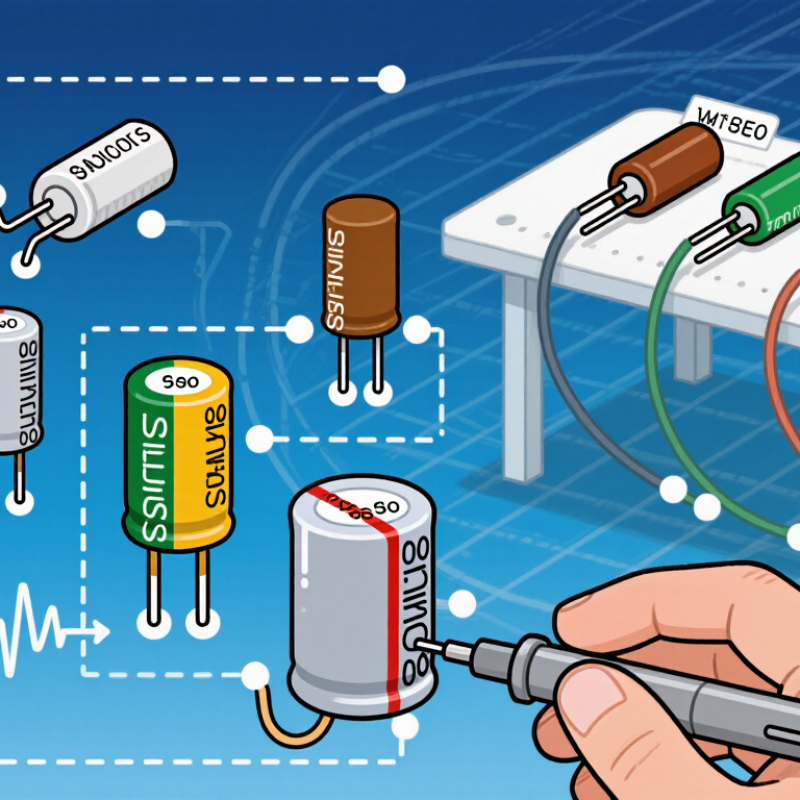
Table of Contents [Hide]
Understanding the Role of Compensation Capacitors
Compensation capacitors shape an amplifier’s feedback loop. They trade bandwidth for stability, controlling phase margin, noise gain, and transient response. In practice, the right value prevents ringing when a load changes suddenly. Too much capacitance can make the circuit sluggish.
Start with ten checks: calculate the target pole, inspect the amplifier’s open-loop gain, and verify the feedback resistor values. Then review dielectric type, tolerance, voltage rating, temperature drift, leakage, package size, and parasitic inductance. Measure the actual capacitor, not only its printed value. A 10 nF part can behave differently at high frequency. Keep its traces short.
The 2024 WSTS Spring Forecast places global semiconductor sales at 588.4 billion dollars for 2024, increasing pressure on compact, fast control circuits. A 2024 global ceramic-capacitor market outlook also projects continued growth through 2028, driven by automotive, communications, and industrial electronics. More components do not guarantee better control. I have seen designs fail because engineers copied a compensation value from another layout. That shortcut is tempting. Use network analysis, load-step testing, and frequency-response measurements instead. Check stability across temperature and production tolerance. My own caution is simple: simulations often look cleaner than hardware. A few nanohenries of routing can change the result. Evaluate the complete loop, including the sensor, load, connector, and power network.
10 Tips for Choosing Compensation Capacitors - Understanding the Role of Compensation Capacitors
| Tip | Selection Factor | Why It Matters | Practical Selection Guidance | Key Checks |
|---|---|---|---|---|
| 1 | Define the compensation function | A compensation capacitor can introduce a pole, zero, or phase lead/lag that changes loop stability, bandwidth, and transient response. | Identify whether the capacitor is used for dominant-pole compensation, high-frequency noise reduction, feedback compensation, or stabilization of a switching-control loop before selecting its value. | Loop type Target bandwidth |
| 2 | Choose the capacitance value | Capacitance directly affects pole and zero locations. An excessively large value may slow the circuit, while an insufficient value may leave inadequate phase margin. | Calculate the required value from the relevant resistance and target frequency. For a simple RC network, use f = 1/(2πRC), then verify the result with simulation and measurement. | Pole frequency Settling time |
| 3 | Select a suitable dielectric | Dielectric type affects capacitance stability, losses, voltage dependence, aging, and temperature behavior. | Use stable dielectric technologies for precision or timing-sensitive compensation. High-permittivity ceramic capacitors can offer small size but may show significant capacitance change with DC bias and temperature. | DC-bias effect Temperature stability |
| 4 | Check tolerance and effective capacitance | The actual capacitance may differ from the marked value because of production tolerance, applied voltage, temperature, and aging. | Evaluate the complete capacitance range under the circuit's operating conditions. Use the effective capacitance rather than the nominal value when calculating loop poles or zeros. | Worst-case range Operating bias |
| 5 | Verify voltage rating and derating | Exceeding the rated voltage can cause dielectric degradation, excessive leakage, capacitance loss, or catastrophic failure. | Select a voltage rating above the maximum steady-state and transient voltage. For ceramic capacitors, derating is especially important because capacitance can decrease as applied DC voltage increases. | Maximum voltage Transient margin |
| 6 | Consider ESR and ESL | Equivalent series resistance and inductance add parasitic poles and zeros, limiting high-frequency performance and potentially reducing stability. | Review impedance versus frequency rather than relying only on the capacitance value. Keep high-frequency compensation paths short and use a package appropriate for the intended frequency range. | Impedance curve Self-resonance |
| 7 | Assess leakage current | Leakage can shift DC operating points, alter bias currents, and change the expected time constant in high-impedance compensation networks. | Use a low-leakage capacitor when the compensation node has high resistance or when the circuit operates with very small bias currents. Include leakage in the worst-case error analysis. | Node impedance Bias-current error |
| 8 | Check temperature and aging behavior | Capacitance drift changes pole and zero frequencies, which can affect phase margin, crossover frequency, and transient behavior over time. | Specify the operating temperature range and expected service life. Include temperature coefficient, aging rate, and environmental conditions in the stability analysis when they are relevant. | Temperature range Long-term drift |
| 9 | Optimize PCB layout | Trace inductance, parasitic coupling, and noisy return paths can undermine the intended compensation network and introduce unwanted feedback. | Place the capacitor close to the associated feedback, amplifier, or control pins. Minimize loop area, avoid routing sensitive compensation traces beside high-current nodes, and provide a clean return path. | Short connections Noise coupling |
| 10 | Validate stability in the final design | Simulation models may not fully represent component parasitics, layout effects, load variation, or production tolerances. | Test minimum and maximum loads, input and output extremes, temperature limits, startup, shutdown, and fast transients. Confirm adequate phase margin, gain margin, overshoot, and settling behavior with the assembled hardware. | Worst-case test Phase margin |