
-
- Products
- Indoor Household Cords
- Appliance Cords
- General Purpose Short-Length Cords
- General Purpose Extension Cords
- Landscape & Decorating Cords
- Bright Color Extension Cords
- Oil-Resistant Extension Cords
- Cold-Flex Extension Cords
- VividFlex Power Cords
- EXTREME All-Weather Cords
- Cord Management
- Task Lights
- Adapters & GFCI Devices
- Where to Buy
- About
- Careers
- Glossary
- Catalog


How to Choose a Horizontal Shaft Concrete Mixer?
Choosing the right Horizontal Shaft Concrete Mixer begins with the material, not the machine brochure. Concrete remains one of the world’s most widely used construction materials. The Global Cement and Concrete Association reports annual concrete production at roughly 14 billion cubic metres. That scale makes mixing quality a practical issue, not a minor specification. A poorly matched mixer can leave dry pockets, uneven moisture, or excessive residue along the trough.
The first questions should concern output, aggregate size, mix design, and available installation space. A horizontal shaft mixer usually provides strong shearing action and controlled movement across the mixing chamber. This suits stiff concrete, fiber-reinforced mixtures, and many precast applications. However, performance depends on paddle geometry, shaft speed, wear protection, and loading sequence. More power is not always better. It may increase energy use without improving consistency.
Industry guidance supports careful verification. ACI 304R discusses concrete batching, mixing, and transporting practices, while ASTM C94 emphasizes consistency and performance in ready-mixed concrete production. The International Energy Agency also identifies cement production as responsible for about 7% of global energy-related CO2 emissions. Efficient mixing therefore deserves attention, although mixer energy is only one part of the total footprint.
Look for measurable evidence. Ask for batch-cycle data, tested capacity, moisture-control procedures, and service records. Inspect the discharge gate and liners closely. Small gaps can become expensive problems. Operator experience matters too. A technically excellent mixer can still fail when cleaning routines, calibration, or loading habits are ignored. No single model fits every site. The best choice balances throughput, mix quality, maintenance access, safety, and long-term operating cost. Some decisions remain uncertain until the actual materials are tested. That is a limitation worth admitting.
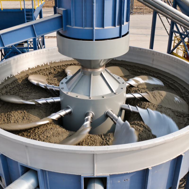
Table of Contents [Hide]
Define the Mixing Requirements and Concrete Production Goals
How to Choose a Horizontal Shaft Concrete Mixer?
Define the Mixing Requirements and Concrete Production Goals
Begin with the concrete, not the mixer. The Global Cement and Concrete Association reports that about 14 billion cubic metres of concrete are produced globally each year. This scale hides major differences between projects. A precast plant may require stiff, low-slump mixes, while a foundation crew may need faster discharge and flexible batch sizes. Record target output per hour, batch volume, slump, aggregate size, and mixing time.
The Global Cement and Concrete Association reports that about 14 billion cubic metres of concrete are produced globally each year.
Horizontal shaft mixers suit dense mixes because their paddles create strong horizontal circulation. However, capacity alone does not prove performance. ASTM C94/C94M and ACI 304R emphasize consistent proportions, uniform mixing, and controlled delivery. Test the intended recipe with local sand moisture and aggregate grading. Watch the discharge gate closely. Dry pockets or stone buildup can reveal poor mixing before laboratory results do.
Define acceptable variation before requesting quotations. A practical trial should check slump, air content, visual uniformity, and compressive strength. Measure energy use and cleaning time too. These details affect production more than brochure figures. Industry experience suggests that rushed batch cycles often create hidden quality losses. I have seen operators increase speed, then spend longer correcting uneven loads. That is not real productivity. Leave room for mistakes. Moisture changes during a wet week can defeat an otherwise accurate production plan. Recheck the targets after the first trials.