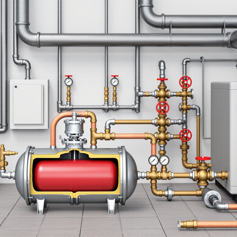
| Closed Hydronic Heating | Water or water–glycol mixture | Fluid volume increases as the heating system temperature rises, causing pressure to increase in a sealed circuit. | Heating-system diaphragm or replaceable-bladder expansion vessel | Use a membrane compatible with the system fluid and operating temperature. For glycol mixtures, verify chemical compatibility. | Approximately 60–90°C in many building heating systems; the actual design temperature depends on the heat source and controls. | System water volume, minimum and maximum operating temperatures, static system height, cold fill pressure, safety-valve setting, and glycol concentration. | Install on the suction side of the circulation pump where possible. The vessel pre-charge must be set with the water side isolated and depressurized, according to the system design. |
| Domestic Hot Water | Potable water | Heating water in a closed or check-valve-protected supply expands and can raise pressure when backflow is prevented. | Potable-water-rated thermal expansion vessel | Use a certified potable-water diaphragm or bladder made from materials approved for drinking-water contact in the applicable market. | Usually approximately 50–60°C at the storage or distribution system, subject to local hygiene and safety requirements. | Water-heater volume, cold-water temperature, hot-water setpoint, incoming pressure, pressure-reducing valve setting, and allowable maximum pressure. | Do not use a heating-only vessel in a potable-water system. Install downstream of a check valve or pressure-reducing valve and upstream of the water heater where the system design requires it. |
| Solar Thermal Heating | Water–glycol solar fluid or water, depending on system design | Solar collectors can reach high stagnation temperatures, producing significant fluid expansion and possible vapor formation. | High-temperature solar expansion vessel, normally diaphragm type | Membrane must tolerate the specified solar fluid, elevated temperature, and repeated thermal cycling. A separate cooling or intermediate vessel may be required. | Normal operation may be approximately 70–120°C; stagnation temperatures can be substantially higher depending on collector design. | Collector and pipe volume, fluid expansion coefficient, minimum and maximum temperatures, static height, system pressure limits, vapor reserve, and safety-valve setting. | Confirm the vessel temperature rating and glycol compatibility. Protect the vessel from excessive collector heat when required by the system manufacturer or design standard. |
| Closed Chilled-Water System | Chilled water or water–glycol mixture | Pressure changes occur because of fluid temperature variation, system filling, and changes in system volume in a closed circuit. | Diaphragm or bladder expansion vessel rated for chilled-water service | Use a membrane compatible with glycol concentration and low-temperature operation. Select insulation or vapor protection where condensation may occur. | Commonly approximately 5–15°C, with the exact range determined by the cooling equipment and design conditions. | System volume, fluid concentration, minimum and maximum temperatures, static height, fill pressure, operating pressure, and relief-valve setting. | Install and insulate the vessel to prevent surface condensation. The connection point should be selected to maintain stable pressure throughout the chilled-water circuit. |
| Boiler Primary Circuit | Water or water–glycol mixture | Heat input in the boiler circuit increases fluid temperature and volume while the circuit remains closed. | Heating-rated expansion vessel sized for the primary circuit | Verify temperature, pressure, and fluid compatibility with the boiler circuit and any corrosion-inhibitor or glycol additive. | Often approximately 70–100°C, although the maximum design temperature may be higher depending on the boiler type. | Primary-loop volume, boiler operating temperature, cold fill pressure, system height, maximum working pressure, and safety-valve setting. | Do not size only from boiler output. Include the boiler, connected pipework, heat exchangers, and any buffer or low-loss header volume. |
| Buffer Tank or Thermal Storage System | Water or water–glycol mixture | Large stored-water volume creates a substantial expansion volume as the tank cycles between its minimum and maximum temperatures. | Large-capacity diaphragm or bladder expansion vessel; multiple vessels may be used where appropriate | Membrane compatibility must match the fluid, maximum temperature, and expected number of thermal cycles. | Commonly approximately 30–95°C, depending on whether the tank serves heating, renewable-energy, or heat-recovery equipment. | Total stored and connected water volume, minimum and maximum tank temperatures, static height, pressure limits, and available installation space. | Include the full tank volume in the calculation. Check connection size, vessel acceptance volume, and whether multiple vessels require balanced connection arrangements. |
| Pressure-Boosting or Domestic Water Supply | Potable cold water | The vessel reduces pump cycling and absorbs small pressure or flow fluctuations in a pressurized water-supply system. | Potable-water pressure vessel with diaphragm or replaceable bladder | Use drinking-water-approved materials and a membrane designed for frequent cycling and the specified pressure range. | Normally close to the incoming cold-water temperature, commonly approximately 5–25°C depending on location. | Pump flow rate, pump start and stop pressures, required drawdown, expected demand cycles, inlet pressure, and maximum working pressure. | Set pre-charge in relation to the pump control pressures. The vessel is primarily for pressure stabilization and drawdown, not for absorbing heating-system expansion unless specifically designed for that purpose. |
| Fire-Protection or Sprinkler Water System | Water, subject to the system design | Small temperature-related volume changes and pressure maintenance requirements can affect supervisory pressure in a closed fire-protection pipe network. | Expansion or pressure-maintenance vessel specifically permitted by the applicable fire-protection design | Material and construction must comply with the governing fire-protection requirements and local authority approvals. | Usually near ambient temperature, but the design must account for the full expected environmental temperature range. | Trapped system volume, ambient temperature range, pressure-maintenance arrangement, maximum allowable pressure, and applicable fire-protection rules. | Do not substitute a general-purpose heating or potable-water vessel without confirming approval and compatibility with the fire-protection design. |
| Process or Industrial Closed Loop | Water, glycol solution, heat-transfer fluid, or another approved process liquid | Thermal expansion, pressure fluctuation, and fluid contraction can affect equipment integrity and process stability. | Industrial diaphragm, bladder, or piston-type expansion vessel selected for the specific process fluid | Confirm membrane, coating, and elastomer compatibility with the chemical composition, concentration, temperature, and cycle frequency. | Application-specific; the complete minimum and maximum temperature range must be used for selection. | Fluid density and expansion coefficient, system volume, temperature range, operating pressure, design pressure, allowable pressure variation, and safety-device settings. | Use the fluid manufacturer’s data for expansion properties. Check material compatibility, fatigue life, certification, corrosion allowance, and maintenance access before final selection. |