
-
- Products
- Indoor Household Cords
- Appliance Cords
- General Purpose Short-Length Cords
- General Purpose Extension Cords
- Landscape & Decorating Cords
- Bright Color Extension Cords
- Oil-Resistant Extension Cords
- Cold-Flex Extension Cords
- VividFlex Power Cords
- EXTREME All-Weather Cords
- Cord Management
- Task Lights
- Adapters & GFCI Devices
- Where to Buy
- About
- Careers
- Glossary
- Catalog


How to Create Exterior Home Renderings?
Creating Exterior Home Renderings is more than placing a house inside a polished digital scene. It is a practical visual process that connects architectural drawings with the client’s future experience. A successful rendering should show scale, materials, daylight, landscaping, and the relationship between the home and its surroundings. The front path should feel walkable. The window reflections should appear believable. Even a small shadow can affect the entire impression.
Alex Hogrefe, an architectural visualization artist and educator, offers a useful principle: “The image should communicate the design, not compete with it.” This idea matters when choosing camera height, sky conditions, textures, and decorative details. A dramatic sunset may attract attention, but it can also hide poor proportions or unclear construction choices. Clear evidence matters more than visual excitement.
The process usually begins with accurate plans and reference photographs. Designers then build the exterior model, apply realistic materials, set lighting, and test several viewpoints. Brick should show subtle variation. Concrete should not look perfectly clean. Trees need irregular branches, not repeated digital shapes. Small imperfections create credibility.
Still, no rendering is completely objective. A carefully chosen camera can make a narrow entrance appear generous. Bright landscaping can distract from weak architecture. Therefore, review the image with a builder, designer, and client. Ask what feels unclear. Revise it.
Good Exterior Home Renderings do not promise perfection. They reduce uncertainty, reveal design problems, and help people imagine daily life before construction begins.
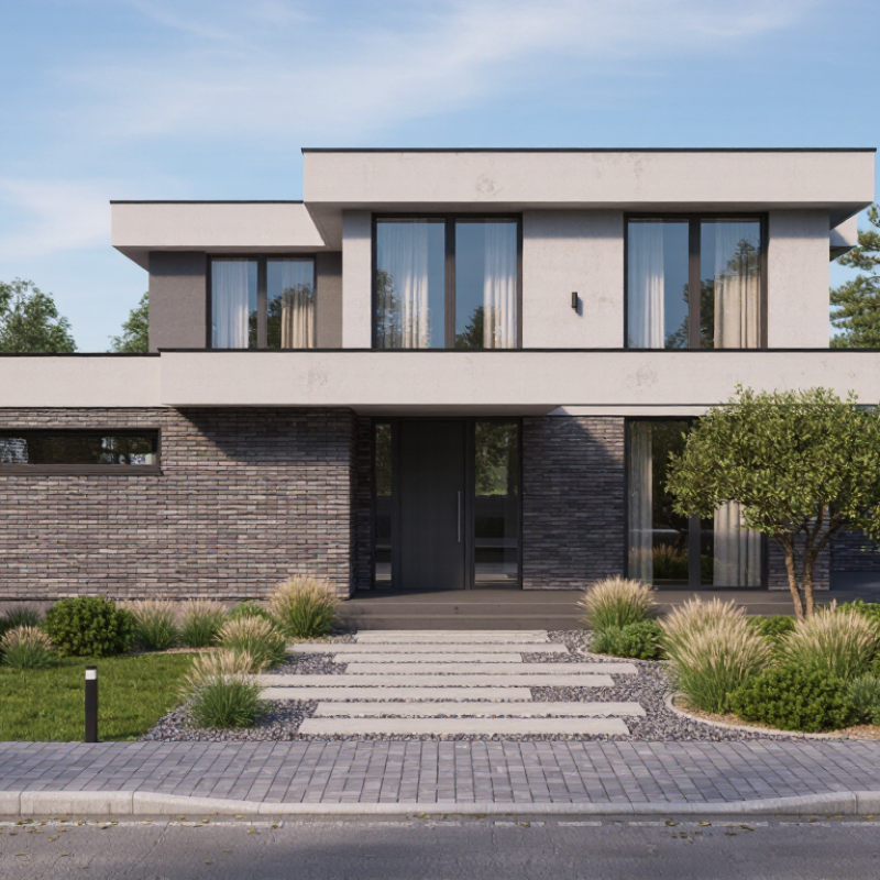
Table of Contents [Hide]
Define the Rendering Brief with 1:1 Scale, Views, and Required LOD
How to Create Exterior Home Renderings?
Before modeling, define a rendering brief that treats the house as measurable evidence, not decoration. Set every major dimension at a 1:1 scale, including wall height, roof pitch, window size, and site boundaries. Record the source of each measurement and mark uncertain areas clearly. Without this discipline, attractive images can still misrepresent the building. I once underestimated a porch depth by several centimeters. That small error changed the entrance’s visual balance.
Choose views that explain the exterior from practical human positions. An entry view should show the door, path, steps, and nearby lighting. A corner view can reveal wall depth, roof edges, and the relationship between floors. Add a rear or garden view when outdoor circulation matters. Mark camera height, lens range, and orientation in the brief. These details prevent accidental distortion. Too many views waste time.
Specify the required LOD before production begins. LOD defines how much physical detail the model must contain. For early approval, accurate massing, openings, roof forms, and materials may be enough. For construction-focused images, include window frames, drainage details, joints, railings, and realistic ground transitions. Link each view to its required LOD, lighting condition, and material notes. Yet the brief should remain flexible. Design decisions often change after the first rendering. Review the images against site photos and drawings. Perfect briefs do not exist.