
-
- Products
- Indoor Household Cords
- Appliance Cords
- General Purpose Short-Length Cords
- General Purpose Extension Cords
- Landscape & Decorating Cords
- Bright Color Extension Cords
- Oil-Resistant Extension Cords
- Cold-Flex Extension Cords
- VividFlex Power Cords
- EXTREME All-Weather Cords
- Cord Management
- Task Lights
- Adapters & GFCI Devices
- Where to Buy
- About
- Careers
- Glossary
- Catalog


What Is a Single Stage Pump and How Does It Work?
A Single Stage Pump moves liquid through one impeller before discharge. Its design looks simple, but performance depends on details. Impeller diameter, shaft speed, casing shape, and system resistance all matter.
The U.S. Department of Energy reports that pumping systems can consume 25% to 50% of industrial facility energy. Its pump-system guidance also emphasizes correct sizing, throttling control, and maintenance. Hydraulic Institute standards provide reference methods for pump testing, efficiency, vibration, and application selection. Meanwhile, Grand View Research’s 2024 centrifugal pump analysis identifies strong demand from water treatment, building services, agriculture, and industrial processing. These reports describe market direction, not every installation. Real results still depend on field conditions.
A Single Stage Pump typically draws liquid through its suction nozzle. The rotating impeller adds velocity. The casing then converts much of that velocity into pressure. Picture water entering near the shaft and leaving along the casing’s outer edge. That path explains the pump’s basic operation.
Pump engineer Igor J. Karassik is widely credited with saying, “The pump is the heart of the system.” The comparison remains useful, though imperfect. A pump cannot compensate for blocked pipes, poor alignment, or an undersized motor. Engineers must examine the entire system, not just the pump curve. This guide will explain construction, operating principles, advantages, limitations, efficiency concerns, and practical selection criteria. It will also question a common assumption: simpler equipment is not always easier to operate well.
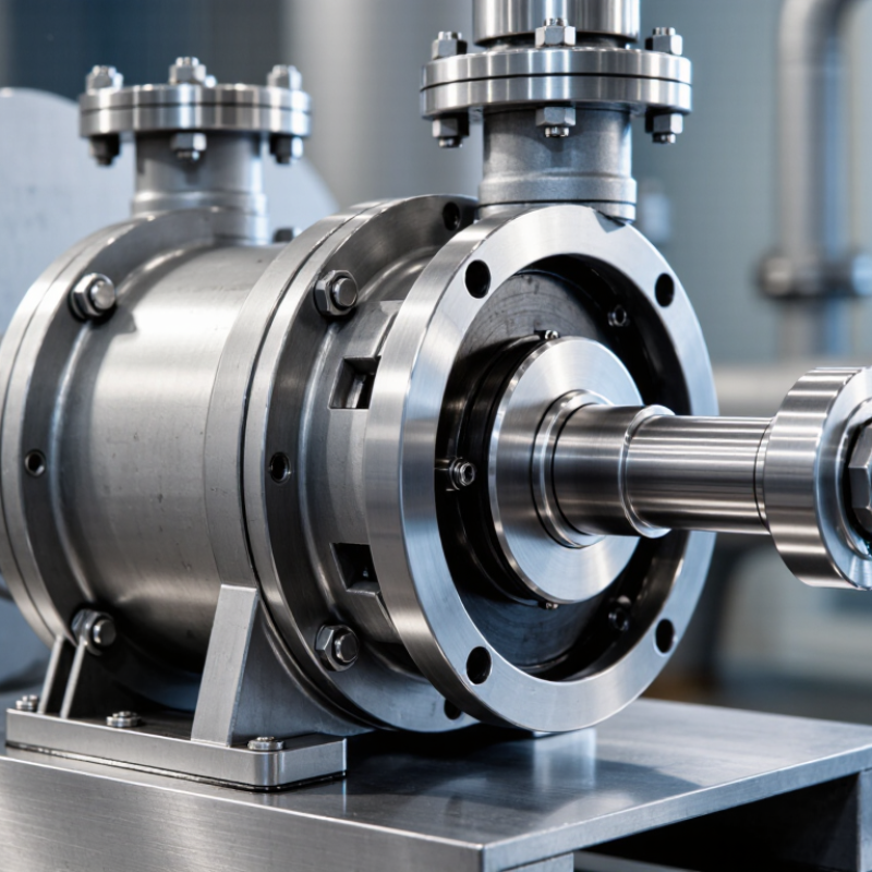
Table of Contents [Hide]
Single-Stage Pump Definition: One Impeller for Low-to-Medium Head Service
What Is a Single Stage Pump and How Does It Work?
A single-stage pump uses one impeller to move liquid through a casing. This design provides low-to-medium head service for many water and process applications. As liquid enters the suction eye, the rotating impeller accelerates it outward. The casing then converts much of that velocity into pressure. Pressure rises. The discharge pipe carries the liquid toward the system.
Single-stage pumps are often chosen for circulation, drainage, irrigation, and general transfer duties. Their simple construction usually allows easier inspection and routine maintenance. A technician can check the shaft seal, bearings, coupling, and impeller without managing several impeller stages. However, the actual head depends on impeller diameter, speed, flow rate, and system resistance. A pump rated for 30 metres of head may deliver much less at a higher flow rate.
In field checks, a pressure gauge and flow reading reveal more than the nameplate alone. Unusual vibration, a rattling sound, or unstable discharge pressure may indicate cavitation, air entry, blockage, or incorrect sizing. Suction piping deserves careful attention. Small leaks can reduce performance before they become obvious. A single-stage pump cannot efficiently handle every high-rise or high-pressure duty. I would recheck the duty point before installation, because a convenient selection can still be wrong. Impeller wear also changes performance over time. That detail is easy to overlook.