
-
- Products
- Indoor Household Cords
- Appliance Cords
- General Purpose Short-Length Cords
- General Purpose Extension Cords
- Landscape & Decorating Cords
- Bright Color Extension Cords
- Oil-Resistant Extension Cords
- Cold-Flex Extension Cords
- VividFlex Power Cords
- EXTREME All-Weather Cords
- Cord Management
- Task Lights
- Adapters & GFCI Devices
- Where to Buy
- About
- Careers
- Glossary
- Catalog


7 Tips for Choosing a BMC Composite Hydraulic Press?
Choosing a Bmc Composite Hydraulic Press is not simply a matter of comparing tonnage and price. The right machine must match the compound, mould design, production volume, and required surface quality. BMC can behave like a stubborn dough when temperature control is poor. It may trap air, flash around the mould, or leave visible flow marks. A press that looks impressive on paper may still waste material on the factory floor.
Composite engineering scholar Dr. Suong V. Hoa offers a useful reminder: “A composite design must survive the manufacturing process.” This principle matters when evaluating a Bmc Composite Hydraulic Press. Buyers should examine pressure stability, platen parallelism, heating uniformity, mould clearance, cycle control, safety systems, and after-sales support. Ask for test data using your actual BMC formulation. Request sample parts, not only brochures. Check how quickly the press reaches its target temperature, and inspect the finished edges under strong light.
There is no perfect machine.
A practical review should also consider maintenance access, energy consumption, operator training, and future mould changes. Some buyers focus heavily on initial cost and overlook downtime. That decision can become expensive. Others select excessive capacity, creating unnecessary energy use and slower movement. The better choice balances force, speed, accuracy, durability, and technical support. These seven tips provide a clear starting point, while leaving room for one honest conclusion: real production trials reveal weaknesses that specifications cannot.
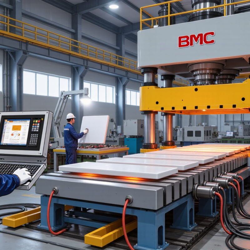
Table of Contents [Hide]
Define BMC Parts by Area, Thickness, Volume, and 5–15 MPa Molding Pressure
Choosing a BMC composite hydraulic press starts with the part, not the machine catalog. Measure the projected molding area, including flash risk and inserts. Multiply this area by a practical molding pressure between 5 and 15 MPa. Then add a sensible safety margin for material variation and uneven loading. A small error here can cause flash, poor filling, or unstable dimensions.
Check part thickness and volume carefully. Thick sections may need slower closing, longer heating, and extra daylight for safe mold handling. High-volume parts require enough shot capacity, reliable dosing, and repeatable platen movement. The mold should sit comfortably on the platen, with space for clamps, ejectors, and operator access. Temperature control matters too. Watch for cold corners, resin sticking, or a dull surface after molding. These details often reveal process problems before inspection data does.
···
A useful press also offers stable pressure control, clear cycle records, and accessible maintenance points. Ask how quickly the system responds when pressure drops during filling. Confirm that the hydraulic system can hold pressure without visible drift. In practice, the first tonnage estimate is rarely perfect. I have seen a compact part need more force because its cavity filled unevenly. Trial molding should challenge the calculation, not merely confirm it. Leave room for tooling changes, future materials, and the occasional design assumption that proves wrong.