
-
- Products
- Indoor Household Cords
- Appliance Cords
- General Purpose Short-Length Cords
- General Purpose Extension Cords
- Landscape & Decorating Cords
- Bright Color Extension Cords
- Oil-Resistant Extension Cords
- Cold-Flex Extension Cords
- VividFlex Power Cords
- EXTREME All-Weather Cords
- Cord Management
- Task Lights
- Adapters & GFCI Devices
- Where to Buy
- About
- Careers
- Glossary
- Catalog


7 Tips for Choosing a Cast Resin Transformer
Choosing a Cast Resin Transformer is a technical decision, not merely a purchase based on price. The right unit must match voltage, load profile, installation conditions, fire requirements, and maintenance expectations. IEC 60076-11 classifies dry-type transformers, while IEEE C57.12.01 defines important insulation and performance requirements. These standards provide a useful starting point.
Market data also shows why careful selection matters. Grand View Research reports continued growth in the global dry-type transformer market, driven by urban infrastructure, renewable energy, and safer indoor installations. MarketsandMarkets identifies similar demand from industrial facilities, commercial buildings, and distribution networks. However, market forecasts vary. They should support decisions, not replace engineering calculations.
Dr. S. V. Kulkarni, a recognized transformer-design specialist, describes transformer design as “a compromise between electrical, mechanical, thermal, and economic requirements.” That principle remains practical when comparing a Cast Resin Transformer. Look closely at seven areas: rated capacity, overload behavior, insulation class, cooling method, noise level, short-circuit strength, and service support.
Small details matter. A dusty plant may need stronger enclosure protection. A hospital may prioritize low emissions and fire safety. A rooftop installation may require careful temperature and ventilation checks. Ask for verified test reports, not attractive brochures.
The choice is rarely perfect. Engineers must balance efficiency, footprint, price, and future expansion. This guide explains how to compare those factors clearly, while recognizing one uncomfortable truth: the cheapest transformer can become the most expensive equipment in the room.
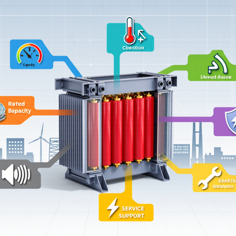
Table of Contents [Hide]
Translate Load Demand into kVA: Include Starting and Harmonic Loads
7 Tips for Choosing a Cast Resin Transformer
Tip 1 Start with measured demand, not connected load. Record voltage, phase configuration, power factor, and peak current from site measurements. For three-phase systems, estimate kVA with √3 × voltage × current ÷ 1,000. Include normal lighting, heating, motors, and control equipment.
Tip 2 Treat starting current as a separate requirement. A motor may draw five to seven times its running current during acceleration. This brief surge can cause voltage dips and nuisance trips. Check locked-rotor current, starting frequency, and the largest motor starting point. Soft starters reduce stress, but they do not erase every design concern.
Tip 3 Add nonlinear loads carefully. Variable-speed drives, rectifiers, data equipment, and UPS systems can create harmonic currents. Review the total harmonic distortion and neutral loading. A transformer can carry the calculated kVA and still run hot. That mistake is common.
Tip 4 Apply realistic diversity factors. Do not simply add every nameplate rating, but avoid optimistic assumptions. Production schedules change.
Tip 5 Allow practical growth capacity, often 15 to 25 percent when future loads are uncertain. More capacity is not automatically better; light loading can affect efficiency and project cost.
Tip 6 Check ambient temperature, altitude, enclosure ventilation, and installation clearances. Cast resin units tolerate demanding environments, but heat still matters.
Tip 7 Verify the final selection with a qualified engineer and commissioning data. A neat spreadsheet can still be wrong. Recheck field measurements after installation, especially when motors or electronic loads behave differently than expected.