-
- Products
- Indoor Household Cords
- Appliance Cords
- General Purpose Short-Length Cords
- General Purpose Extension Cords
- Landscape & Decorating Cords
- Bright Color Extension Cords
- Oil-Resistant Extension Cords
- Cold-Flex Extension Cords
- VividFlex Power Cords
- EXTREME All-Weather Cords
- Cord Management
- Task Lights
- Adapters & GFCI Devices
- Where to Buy
- About
- Careers
- Glossary
- Catalog


7 Tips to Choose the Right Relief Valve Block?
Selecting the right Relief Valve Block is a small decision with serious consequences. It influences isolation, maintenance, leakage control, and emergency response. A poorly matched block can restrict flow, complicate testing, or create an unnoticed pressure path.
Industry demand is also rising. Grand View Research reported that the global pressure relief valve market was valued at approximately USD 4.7 billion in 2023. Its analysis projects continued growth through 2030, driven by stricter process safety expectations and expanding industrial automation. MarketsandMarkets has likewise identified oil and gas, chemicals, power generation, and water treatment as major application sectors. These figures show opportunity, but they do not replace engineering judgment.
Trevor Kletz, a respected process-safety author, warned, “What you don’t know can hurt you.” That warning fits valve-block selection. Engineers must examine pressure rating, temperature range, wetted materials, port configuration, actuation method, and maintenance access. API 520 and API 521 provide important guidance for pressure-relief-system design, while ASME requirements may apply to the protected equipment. Standards are essential. They are not a substitute for field experience.
A useful selection process should also consider vibration, corrosion, installation space, and accidental misalignment. The smallest detail matters. A blocked vent path can become a dangerous oversight. This guide presents seven practical tips for choosing a Relief Valve Block with greater confidence. Still, no checklist is perfect. Actual media behavior, operating history, and inspection findings may challenge the original design assumptions.
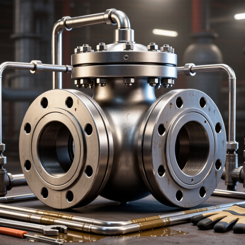
Table of Contents [Hide]
Understand the Role and Application of a Relief Valve Block
7 Tips to Choose the Right Relief Valve Block?
Understand the Role and Application of a Relief Valve Block
A relief valve block connects a pressure relief valve with the protected system. It helps control, isolate, test, or drain the valve during maintenance. Its main duty is simple: release excess pressure before equipment suffers damage. In hydraulic systems, the block may protect pumps, actuators, and compact power units. In pneumatic systems, it can support receivers, manifolds, and process lines. The application decides the design.
Check the system pressure, temperature, fluid type, and required flow rate. Then match the block’s pressure rating and port size. Material compatibility matters, especially with corrosive fluids or high-temperature oil. Examine the internal passage carefully. A narrow passage can restrict relief flow. That mistake is easy to miss. Confirm the valve connection, thread standard, and installation direction. A small mismatch can create leakage or expensive rework.
Consider access for testing and inspection. A visible test port saves time when technicians verify operating pressure. Choose a block that reduces unnecessary joints and possible leak points. If isolation is possible, use a documented procedure and suitable secondary protection. Never close a valve that could disable the only pressure safeguard. Review certificates, inspection records, and pressure-test evidence from the supplier. Field conditions can differ from drawings, so check the actual space, vibration, and maintenance clearance before ordering. A perfect specification can still fail in a cramped installation.