
-
- Products
- Indoor Household Cords
- Appliance Cords
- General Purpose Short-Length Cords
- General Purpose Extension Cords
- Landscape & Decorating Cords
- Bright Color Extension Cords
- Oil-Resistant Extension Cords
- Cold-Flex Extension Cords
- VividFlex Power Cords
- EXTREME All-Weather Cords
- Cord Management
- Task Lights
- Adapters & GFCI Devices
- Where to Buy
- About
- Careers
- Glossary
- Catalog


China Top Lighted Toggle Switch Manufacturer Supplier
Choosing a China Top Lighted Toggle Switch Manufacturer Supplier requires more than comparing unit prices. It requires practical knowledge of switching performance, panel installation, and long-term reliability. A dependable supplier should explain contact materials, actuator design, lamp voltage, terminal construction, and operating life clearly. Buyers need evidence, not polished promises.
Mike Holt, a respected electrical safety educator, says, “Electricity is not forgiving.” That principle matters when selecting a Lighted Toggle Switch for industrial panels, control cabinets, vehicles, and equipment. A bright indicator should remain visible without creating excessive heat. The toggle should move firmly, not feel loose after repeated operation. Terminals should accept secure wiring and resist vibration during daily use.
Details reveal quality. Look for documented current ratings, insulation specifications, temperature limits, and testing procedures. Ask whether each batch receives continuity, illumination, mechanical-cycle, and dielectric-strength checks. Supplier experience also matters. A factory familiar with OEM drawings can adjust bezel colors, terminal layouts, legends, and packaging for different projects.
Still, no switch is perfect for every environment. A model suitable for an indoor control box may fail in moisture, dust, or severe vibration. That limitation deserves attention. Some product pages also use broad claims without test conditions. Careful buyers should question them.
This guide examines how leading Chinese manufacturers and suppliers develop, test, and support Lighted Toggle Switch products. It focuses on technical facts, purchasing risks, customization ability, and service after delivery. The goal is simple: help you choose confidently, but not blindly.
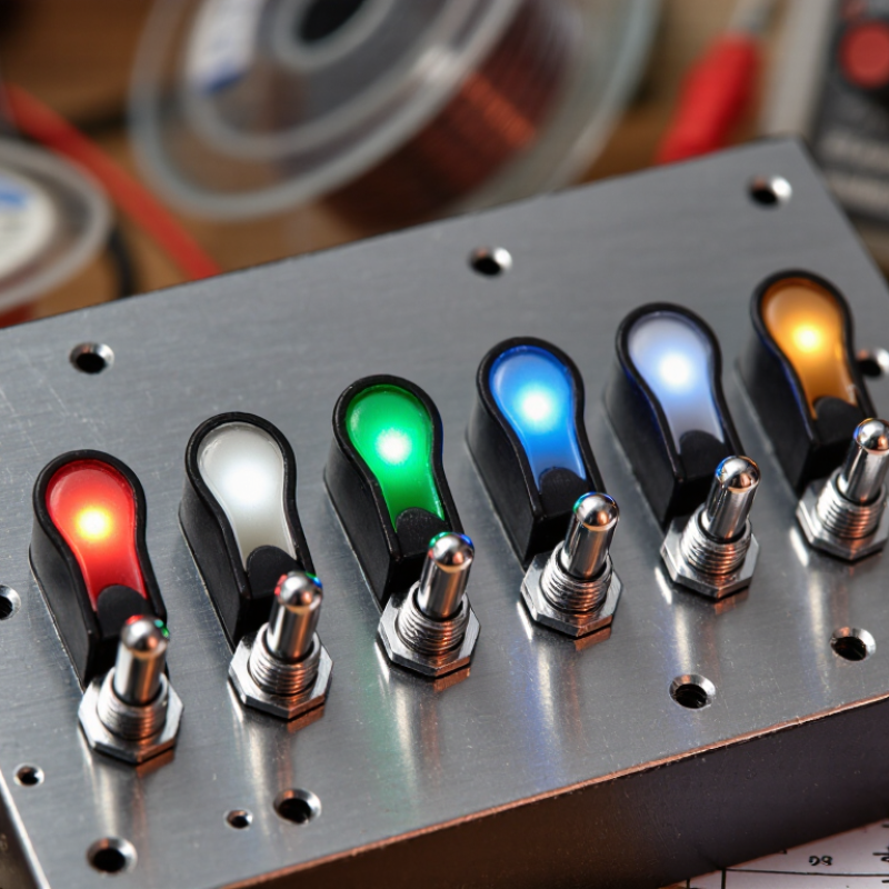
Table of Contents [Hide]
Lighted Toggle Switches: Definition, Types, and Core Features
Lighted Toggle Switches: Definition, Types, and Core Features
A lighted toggle switch combines mechanical switching with visual status indication. Its small lamp or LED shows whether a circuit is active, selected, or ready. This feedback is valuable on control panels, power equipment, vehicles, and testing instruments. Visibility matters, especially in dim workshops or crowded enclosures.
Common types include SPST, SPDT, DPST, and DPDT designs. SPST controls one circuit, while SPDT changes between two circuit paths. DPST and DPDT versions manage two circuits together. Indicator colors often include red, green, amber, and blue, but color meanings should match the equipment plan. A bright indicator is not always better.
Core features include rated voltage, current capacity, contact material, actuator style, and terminal configuration. LED illumination usually consumes less energy than older lamp technology. Check whether the light works independently or only when the load is energized. That detail matters. Waterproof versions may use sealed bodies, protective boots, or panel gaskets. Confirm the actual protection rating instead of trusting general wording.
In supplier evaluation, inspect terminal strength, switching feel, light consistency, and temperature performance. A practical sample test should include repeated operation under the intended load. One overlooked issue is panel thickness; a switch may fit the circuit but fail during installation. Specifications can also be incomplete, so asking for drawings and test data is worthwhile. No single type suits every application.
China Top Lighted Toggle Switch Manufacturer Supplier - Lighted Toggle Switches: Definition, Types, and Core Features
| Data Dimension | Category or Specification | Detailed Information | Typical Selection Considerations |
|---|---|---|---|
| Product Definition | Lighted Toggle Switch | A manually operated electromechanical switch with an integrated lamp or LED indicator. The illumination shows the switch position, circuit status, or power availability. | Confirm whether the indicator should illuminate when the circuit is on, off, or connected to a separate indicator circuit. |
| Operating Mechanism | Maintained action | The toggle remains in the selected position until it is manually moved back. Common circuit functions include ON/OFF and ON/ON. | Suitable for power control, equipment enable functions, and applications requiring a stable operating state. |
| Operating Mechanism | Momentary action | The toggle returns to its normal position after release. Typical functions include OFF-(ON) or ON-(OFF), depending on the contact arrangement. | Often selected for test, reset, jog, start, or temporary activation functions. |
| Common Circuit Function | SPST | Single Pole, Single Throw. It controls one circuit with a simple open or closed function. | Appropriate for basic single-load switching where only one circuit path is required. |
| Common Circuit Function | SPDT | Single Pole, Double Throw. One common terminal switches between two output terminals. | Useful for selecting between two circuits or providing ON/ON or ON-(ON) functions. |
| Common Circuit Function | DPST or DPDT | Double-pole configurations control two electrically separate circuits. DPDT versions can switch each pole between two outputs. | Consider these options when two circuits must be switched together or when polarity or source selection is needed. |
| Illumination Source | LED indicator | LEDs are widely used because they provide long service life, low power consumption, fast response, and multiple color options. | Check LED voltage, polarity, current, color, brightness, and whether an external resistor is required. |
| Illumination Source | Neon indicator | Neon lamps are commonly associated with AC indication and can provide a distinctive warm-colored glow. | Verify the rated voltage, required series components, heat generation, and available panel space. |
| Typical Indicator Voltages | Low-voltage LED options | Common nominal options include 6 VDC, 12 VDC, and 24 VDC. Actual availability depends on the switch design and indicator circuit. | Select an indicator voltage that matches the available supply and follow the specified polarity requirements for LEDs. |
| Contact Rating | Resistive load rating | The allowable current and voltage depend on the contact construction. Typical toggle switch ratings may range from low-current signal loads to several amperes at low-voltage or mains conditions. | Use the manufacturer’s rating for the exact model. Derate the switch for inrush, motor, lamp, inductive, or capacitive loads. |
| Electrical Configuration | Normally open or normally closed contacts | Contacts may be open or closed in the normal position and change state when the toggle is operated. | Match the contact state to the control logic and define the required actuator position before wiring. |
| Terminal Style | Solder, quick-connect, screw, or PCB terminals | Terminal formats support different assembly methods, including hand soldering, crimp connections, field wiring, and printed circuit board mounting. | Choose a terminal style that matches the wiring process, conductor size, installation space, and expected mechanical stress. |
| Mounting Method | Panel mount | Panel-mounted switches are installed through a prepared hole and secured with a nut, threaded bushing, bracket, or locking hardware. | Check the required mounting-hole diameter, panel thickness, anti-rotation feature, and clearance behind the panel. |
| Housing Material | Thermoplastic or metal construction | Insulated thermoplastic housings provide electrical isolation, while metal components may offer added mechanical strength and a different appearance. | Evaluate insulation requirements, impact resistance, temperature exposure, grounding, and environmental conditions. |
| Actuator Style | Standard, bat, paddle, or safety toggle | Toggle actuators vary in length, shape, grip, and protection against accidental operation. Some designs include a protective guard or locking feature. | Select the actuator according to operator ergonomics, available space, visibility, and the risk of unintended switching. |
| Protection Level | Dust and moisture resistance | Some lighted toggle switches include sealing features such as gaskets, boots, or sealed terminals. Protection level is design-specific and must not be assumed from appearance alone. | Review the applicable ingress-protection rating and test conditions when the switch is used outdoors, in machinery, or in damp locations. |
| Mechanical Life | Actuation durability | Mechanical life describes the number of operating cycles the actuator and mechanism can complete without an electrical load. Electrical life may be lower and is load-dependent. | Compare mechanical and electrical life separately, especially for frequent switching or high-inrush applications. |
| Environmental Conditions | Temperature, vibration, and contamination | Performance can be affected by ambient temperature, vibration, shock, dust, humidity, chemicals, and salt exposure. | Confirm the operating and storage temperature ranges and select sealing, materials, and terminals suitable for the installation environment. |
| Typical Applications | Control panels and industrial equipment | Lighted toggle switches are used for machine controls, test instruments, power supplies, audio equipment, control cabinets, and electrical equipment. | Prioritize clear status indication, reliable contact performance, panel fit, and compatibility with the control voltage. |
| Safety and Compliance | Standards and approvals | Depending on the market and application, switches may be evaluated against requirements for electrical safety, insulation, flammability, EMC, and environmental performance. | Request documentation for the exact part, including ratings, test conditions, approval marks, and installation instructions. |
| Selection Checklist | Key parameters to confirm | Define circuit function, poles and throws, maintained or momentary action, load type, voltage, current, indicator color, indicator voltage, terminal type, mounting size, protection needs, and operating environment. | Use the complete electrical and mechanical specification rather than selecting a switch by appearance or nominal size alone. |
Note: Electrical ratings, dimensions, indicator requirements, protection levels, and service life vary by exact switch construction. Always verify the relevant technical datasheet before installation or mass production.