
-
- Products
- Indoor Household Cords
- Appliance Cords
- General Purpose Short-Length Cords
- General Purpose Extension Cords
- Landscape & Decorating Cords
- Bright Color Extension Cords
- Oil-Resistant Extension Cords
- Cold-Flex Extension Cords
- VividFlex Power Cords
- EXTREME All-Weather Cords
- Cord Management
- Task Lights
- Adapters & GFCI Devices
- Where to Buy
- About
- Careers
- Glossary
- Catalog


What Is a CCS2 Charging Station?
A CCS2 charging station is a direct-current fast charger built around the Combined Charging System’s Type 2 connector. You may see one beside a motorway, at a depot, or in a public parking area. Its thick cable carries both AC and DC contacts, while the charger communicates with the vehicle before power flows. The plug may look familiar, but compatibility depends on the car, station, and charging protocol working together.
Christian Hahn, Secretary General of CharIN, is an industry voice on charging-system interoperability. A practical way to express that principle is: “A reliable CCS2 charging station must work smoothly with the vehicle, not just offer a high power rating.” This is a paraphrase, not a verbatim quotation. It points to a detail drivers can feel: a session that starts cleanly matters more than a peak figure printed on a screen.
Power ratings often range from moderate fast charging to several hundred kilowatts, yet the car usually sets the limit. Battery temperature, state of charge, and site capacity can reduce the real charging speed. A 350-kilowatt station cannot make every vehicle charge at 350 kilowatts. Not even close, sometimes. This guide explains the connector, charging process, power levels, and practical checks before a stop. It also considers a limitation worth remembering: station labels do not guarantee the same charging experience at every site.
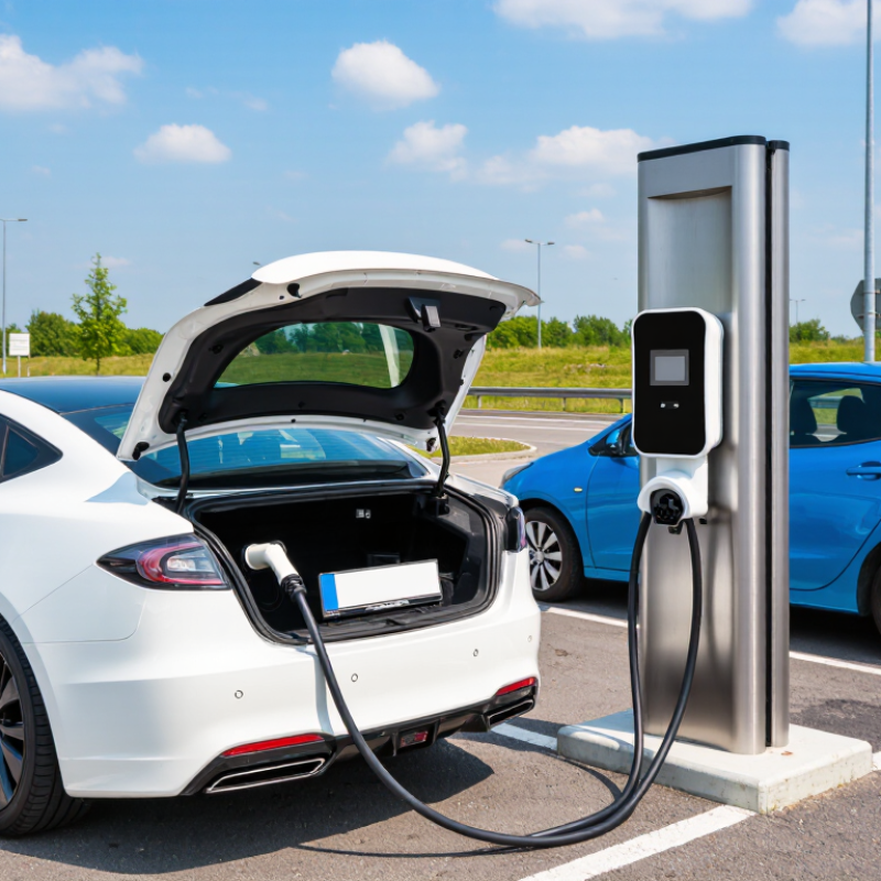
Table of Contents [Hide]
Definition and Purpose of a CCS2 Charging Station
A CCS2 charging station is equipment designed to charge electric vehicles that use the Combined Charging System Type 2 connection. Its plug combines a Type 2-shaped upper section with two larger DC contacts below. Those contacts allow the station to supply direct current to a compatible vehicle. The station and vehicle communicate before charging begins, checking factors such as voltage and the battery’s charging limits.
That matters.
The station’s purpose is to transfer energy safely and manage the charging session, not to guarantee a particular charging speed. Actual power depends on the station’s capacity, the vehicle’s limits, battery temperature, and its current state of charge. For example, a car arriving with a cold battery may initially accept less power, even at a high-capacity station.
The display may show the station’s maximum rating, but the vehicle often draws less. I find this detail easy to overlook when comparing chargers. A CCS2 station is therefore most useful when its connector and output suit the vehicle, and when its cable can reach the parking position comfortably.