
-
- Products
- Indoor Household Cords
- Appliance Cords
- General Purpose Short-Length Cords
- General Purpose Extension Cords
- Landscape & Decorating Cords
- Bright Color Extension Cords
- Oil-Resistant Extension Cords
- Cold-Flex Extension Cords
- VividFlex Power Cords
- EXTREME All-Weather Cords
- Cord Management
- Task Lights
- Adapters & GFCI Devices
- Where to Buy
- About
- Careers
- Glossary
- Catalog


Why Choose a Quick Coupler for Global Sourcing?
Global sourcing is no longer judged by purchase price alone. Buyers now examine delivery reliability, equipment uptime, safety, and supplier support. The World Bank’s Logistics Performance Index 2023 highlights customs, infrastructure, shipment quality, and timeliness as critical logistics factors. These concerns become practical on a construction site. A delayed adapter can leave a 20-ton excavator idle beside a trench.
A Quick Coupler can simplify attachment changes across different machines and job requirements. Operators may switch from a bucket to a breaker within minutes, when the coupler matches the carrier, pin geometry, hydraulic pressure, and attachment weight. ISO 13031:2016 provides safety requirements for Quick Couplers used with earth-moving machinery. It should guide technical evaluation, not replace it. Product certificates matter. Field verification matters more.
Global suppliers also face changing freight routes and uneven after-sales support. The DHL Global Connectedness Report 2024 shows that international trade remains deeply connected, yet supply chains still experience disruption and regional concentration. A reliable sourcing decision therefore requires more than a polished catalog. Buyers should inspect locking indicators, hose protection, spare-part availability, inspection records, and operator training. Small details matter.
No supplier can remove every risk. A low-cost coupler may create hidden maintenance costs. A premium model may be excessive for lighter work. This is where experience improves the decision. Comparing tested performance, lifecycle cost, and local service capacity helps buyers choose a Quick Coupler with greater confidence. Some assumptions will still need review. That is normal in responsible global sourcing.
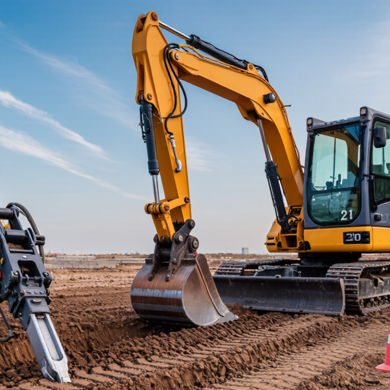
Table of Contents [Hide]
What Is a Quick Coupler and How Does It Work?
A quick coupler is a mechanical connection that joins equipment, hoses, or attachments without lengthy disassembly. Its two halves align, lock, and create a sealed passage for fluid, air, or mechanical force. Many fluid couplers use sleeves, balls, or threaded locking rings to prevent accidental separation. Some designs include shutoff valves. When disconnected, these valves limit leakage and keep contaminants outside. It sounds simple. But fit matters.
In field use, an operator retracts the sleeve, inserts the matching plug, and releases the sleeve. A click usually confirms engagement, but visual inspection remains essential. The connection should sit evenly, resist movement, and show no damaged seal. Under pressure, testing must follow the supplier’s stated procedure and the equipment’s operating limits. I have seen small grit cause a poor seal during repeated hose changes. Cleaning the face before coupling often prevents this avoidable problem. Still, no coupler suits every application.
For global sourcing, buyers should compare working pressure, temperature range, flow needs, materials, and interface dimensions. Metric and imperial measurements can look similar while remaining incompatible. That detail deserves a written check. Ask for drawings, test records, traceability information, and clear installation instructions. A lower purchase price may bring slower maintenance or difficult replacement later. My own selection errors taught me to verify the complete assembly, not only the coupler. I now record that check beside the purchase order.
Why Choose a Quick Coupler for Global Sourcing? - What Is a Quick Coupler and How Does It Work?
| Data Dimension | Typical Data or Range | How It Works or Why It Matters | Global Sourcing Consideration |
|---|---|---|---|
| Product definition | A detachable connector for transferring fluids or gases between hoses, pipes, tools, or equipment | Two mating halves connect and disconnect without permanently joining the lines | Confirm the intended medium, operating conditions, connection standard, and required interchangeability |
| Common applications | Hydraulic machinery, pneumatic tools, agricultural equipment, construction equipment, test systems, and process lines | The coupler enables fast equipment changes, maintenance, and temporary connections | Select a design tested for the relevant industry, fluid, temperature, pressure, and working environment |
| Connection mechanism | Sleeve-lock, ball-lock, screw-to-connect, push-to-connect, or cam-lock mechanisms | The locking mechanism holds the plug and socket together while internal valves open to allow flow | Check the required connection method, operator access, locking security, and compatibility with existing equipment |
| Valve operation | Valved couplers generally stop flow when disconnected; open-flow designs do not include shut-off valves | When the halves mate, valve poppets or sleeves move open; when separated, they close to limit fluid loss | Use a valved type where spill prevention, contamination control, or operator safety is important |
| Nominal connection size | Common hydraulic and pneumatic sizes include approximately 1/8 in to 2 in nominal port size | Port size influences flow capacity, pressure drop, physical dimensions, and hose compatibility | Specify both nominal size and thread standard; similar-looking sizes may not be interchangeable |
| Typical working pressure | Approximately 10 to 700 bar, depending on design, size, material, and service | Working pressure is the pressure permitted during normal operation and is not the same as burst pressure | Request pressure ratings at the actual operating temperature and verify a suitable safety margin |
| Flow capacity | Often about 5 to 300 L/min for industrial couplers, depending on port size and valve design | Larger flow paths generally reduce restriction, while valves and internal geometry create pressure loss | Compare flow curves or pressure-drop data rather than selecting by port size alone |
| Fluid compatibility | Hydraulic oil, compressed air, water, coolant, chemicals, and other application-specific media | The fluid can affect seal swelling, corrosion, leakage, pressure rating, and service life | Provide the exact fluid type, concentration, cleanliness level, and temperature range before sourcing |
| Typical materials | Carbon steel, stainless steel, brass, aluminum, engineering plastics, and elastomeric seals | Material selection determines strength, corrosion resistance, weight, temperature capability, and cost | Request material certificates, coating details, seal material, and corrosion-resistance information where required |
| Temperature range | Common general-purpose ranges are approximately −20°C to +100°C; specialized designs may operate outside this range | Temperature changes can alter seal performance, material strength, and allowable working pressure | Evaluate both ambient temperature and fluid temperature, including short-duration temperature peaks |
| Leakage control | Valved designs can minimize external leakage during disconnection; actual leakage depends on design and condition | Seals and shut-off valves close the flow path and help reduce fluid release and air ingress | Define allowable leakage, cleanliness requirements, inspection method, and test pressure in the purchase specification |
| Connection cycle life | Can range from hundreds to tens of thousands of cycles, depending on construction and maintenance | Wear occurs at locking components, valve surfaces, seals, and mating interfaces | Ask for cycle-test evidence based on the intended pressure, load, contamination, and connection frequency |
| Connection time | Typically a few seconds for a manual connection when alignment and access are suitable | The operator connects the plug and socket, engages the locking sleeve or mechanism, and checks that the connection is secure | Faster changeover can reduce downtime and labor, especially for equipment using interchangeable tools |
| Thread and interface standards | Common interfaces include metric threads, BSP, NPT, SAE, ISO, and application-specific profiles | The mating profile, thread form, sealing method, and dimensions must match for safe operation | Use technical drawings and gauge verification; do not rely only on nominal thread diameter |
| Safety features | Locking sleeves, safety locks, pressure-relief designs, dust caps, and color or size coding | These features help prevent accidental disconnection, trapped-pressure hazards, and contamination | Match safety requirements to the machinery risk assessment and applicable local regulations |
| Quality verification | Dimensional inspection, pressure testing, leakage testing, material verification, and surface-finish inspection | Testing confirms that the coupler meets the specified performance and interchangeability requirements | Define inspection levels, sampling plans, documentation, packaging, and traceability before placing an order |
| Main sourcing benefit | Reduced downtime, easier maintenance, flexible equipment configuration, and simplified hose or tool replacement | A standardized quick coupler creates a repeatable interface across equipment and service locations | Prioritize documented specifications and validated compatibility over unit price alone |
Note: Performance ranges are representative industrial values. Final selection should be based on the manufacturer's technical data, applicable standards, and the actual operating conditions.