
-
- Products
- Indoor Household Cords
- Appliance Cords
- General Purpose Short-Length Cords
- General Purpose Extension Cords
- Landscape & Decorating Cords
- Bright Color Extension Cords
- Oil-Resistant Extension Cords
- Cold-Flex Extension Cords
- VividFlex Power Cords
- EXTREME All-Weather Cords
- Cord Management
- Task Lights
- Adapters & GFCI Devices
- Where to Buy
- About
- Careers
- Glossary
- Catalog


What Is a Zigbee Wall Switch and How Does It Work?
A Zigbee Wall Switch is a smart control device that replaces, or works beside, a traditional light switch. It communicates through the Zigbee wireless protocol rather than relying on Wi-Fi for every command. In a typical home, the switch connects to a Zigbee hub, which links it with an app, voice assistant, or home automation system. Pressing the switch sends a small radio signal. The hub then activates the connected light, scene, or routine.
The experience feels simple.
Behind the wall, several details matter. Some models require a neutral wire, while others are designed for older wiring. Checking the manufacturer’s wiring diagram is essential. A qualified electrician should handle uncertain electrical connections. Zigbee devices can also form a mesh network, allowing powered devices to pass signals across rooms. This can improve coverage, although thick walls, metal boxes, and interference may reduce performance. The system may not respond perfectly on the first attempt.
Compatibility deserves careful attention. A Zigbee Wall Switch may support one hub but fail to pair with another because brands use different profiles or software features. Before buying, confirm the hub, voltage, load type, and lamp compatibility. Real-world setup can be less tidy than product images suggest. Firmware updates, reset procedures, and local control options also influence reliability. Good installation includes testing manual operation, app control, and recovery after a network outage. Zigbee is efficient and practical, but it is not magic. Understanding its limits helps homeowners choose a safer, more dependable smart lighting solution.
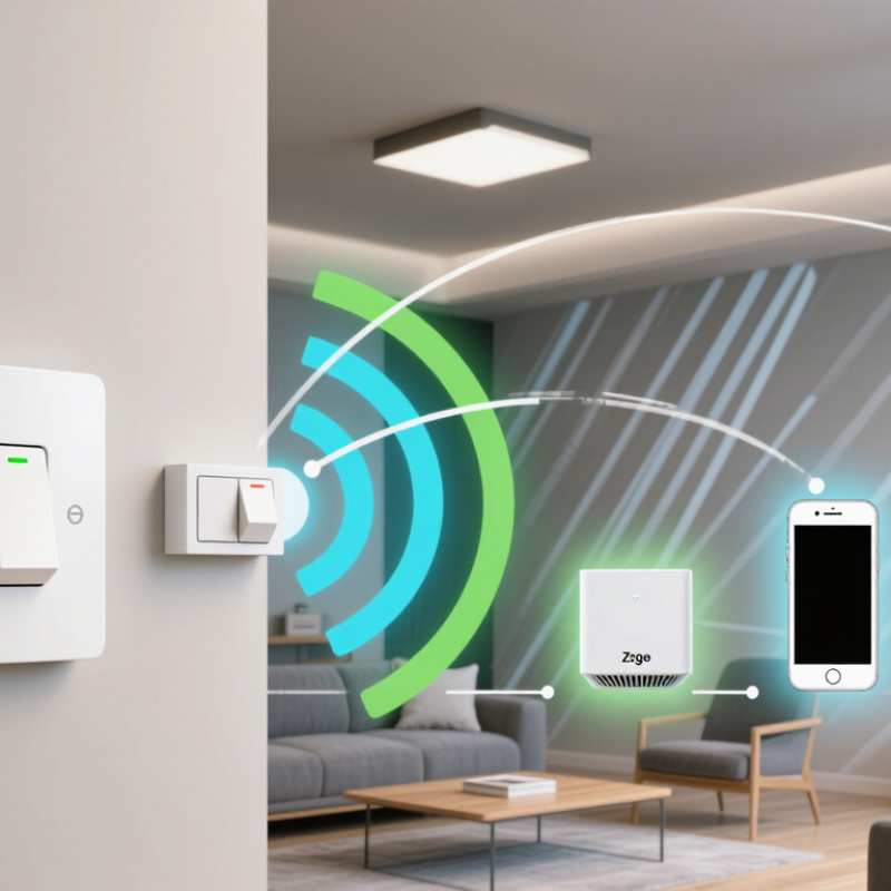
Table of Contents [Hide]
What Is a Zigbee Wall Switch?
A Zigbee wall switch is an in-wall control that operates lights through a low-power wireless network. It usually contains a physical button, a radio module, and an electrical relay. When you press the paddle, the relay changes the circuit’s state. The switch then sends a Zigbee command to a coordinator or compatible hub. In practical use, the lamp may respond before you reach the doorway. That small delay matters.
Unlike a simple wireless button, many Zigbee wall switches also control mains electricity directly. Some models require a neutral wire, while others support older wiring systems. A neutral-free design can be useful, but it may need a minimum lamp load. Otherwise, LEDs may flicker or remain faintly lit. Installation should follow local electrical rules and be completed by a qualified professional.
Zigbee devices can forward messages through a mesh network. This helps signals travel around walls and between rooms. Mesh is not magic. A powered device must remain connected for routing to work reliably. The Zigbee specification also supports AES-128 security, while network performance depends on placement, interference, and hub quality. IoT Analytics reported 16.6 billion connected IoT devices worldwide in 2023, showing why dependable local control remains important. The same report estimated continued growth in 2024. Yet a wall switch is not automatically smart in every home; compatibility and wiring still deserve careful checking.