Top 10 Types of Wire Cable and Their Uses
Wire cable is easy to overlook until a system fails. A brittle jacket, undersized conductor, or unsuitable connector can interrupt power or degrade a signal. Choosing the right type begins with understanding the job: carrying electricity, transmitting data, controlling equipment, or resisting heat, moisture, and movement. These demands explain why building wire, power cable, coaxial cable, twisted-pair cable, control cable, and fiber-optic cable are not interchangeable. Details matter.
Infrastructure investment also shows why cable selection matters beyond a single installation. The International Energy Agency’s 2023 report, Electricity Grids and Secure Energy Transitions, says annual grid investment needs to rise from about USD 330 billion to USD 600 billion by 2030. That figure concerns electricity grids, not the entire wire and cable market, but it highlights the scale of the networks being upgraded. IEC 60228, meanwhile, provides requirements for conductors used in insulated cables, illustrating how technical specifications guide product selection.
This guide introduces ten common wire cable types and their practical uses, from household circuits to industrial controls and communications links. It also points out the features worth checking: conductor material, insulation, shielding, flexibility, and environmental rating. A cable that works well indoors may fail outdoors. Not always obvious. Product labels and installation conditions matter, and this overview cannot replace manufacturer specifications or advice from a qualified professional.
How Cable Types Are Classified: IEC 60228 Defines Conductor Classes 1, 2, 5 and 6
Top 10 Types of Wire Cable and Their Uses
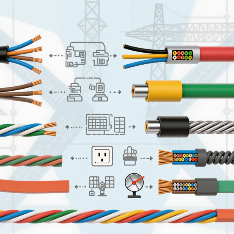
IEC 60228 classifies conductors by construction, not by insulation, voltage, or cable purpose. Class 1 uses a solid conductor, while Class 2 uses strands for rigid installations. Classes 5 and 6 are flexible: Class 6 has finer, more numerous strands for repeated movement. The distinction matters when a cable must bend around a machine or fit inside a crowded control panel.
The IEC 60228 resistance tables show why flexibility can involve a trade-off. For a 1.5 mm² copper conductor, the maximum resistance at 20°C is 12.1 Ω/km for Classes 1 and 2, compared with 13.3 Ω/km for Class 5. These are standard limits, not current-capacity ratings. Installation method, temperature, and grouping still affect safe loading. Fine strands are not automatically better.
The International Energy Agency’s Electricity Grids and Secure Energy Transitions report says annual grid investment needs to rise from about USD 300 billion to more than USD 600 billion by 2030. That expansion will require conductors suited to varied installations, from fixed routes to moving equipment. Real cable selection is sometimes less tidy than a table suggests. Check the required class, conductor size, and installation conditions together.
Copper Conductor Resistance by Cross-Section
Calculated theoretical DC resistance at 20°C for solid copper conductors
Resistance is calculated using copper resistivity of 0.017241 Ω·mm²/m and the formula R = resistivity × 1,000 ÷ cross-sectional area. These are theoretical values, not IEC maximum resistance limits. IEC 60228 conductor classes 1, 2, 5, and 6 describe conductor construction and flexibility; actual resistance also depends on conductor material, stranding, and applicable standard limits.
Building, Power and Armored Cables: NEC Table 310.16 Covers 0–2,000 V
NEC Table 310.16 lists allowable ampacities for insulated conductors rated 0–2,000 volts. It assumes an ambient temperature of 30°C and no more than three current-carrying conductors in a raceway, cable, or earth. These conditions matter. A crowded conduit in a warm ceiling may need ampacity adjustments before a conductor size is selected.
Building wires such as THHN/THWN-2 and XHHW-2 are commonly evaluated using the table, subject to their markings and installation conditions. The table shows separate values for copper and aluminum, with 60°C, 75°C, and 90°C insulation columns. But the highest column is not automatically usable: terminal temperature ratings and other NEC requirements can limit the final ampacity. Armored cable also needs careful review; its conductors, cable construction, and permitted use all affect selection. A table alone is not enough.
For example, a bundle of conductors passing through a hot attic may require correction for both ambient heat and conductor count. The resulting ampacity can be lower than the printed value. A neat table can still mislead. Check the equipment labels, cable markings, and applicable code edition, then have a qualified electrician verify the design. The details are easy to overlook.
Control and Instrumentation Cables: Shielding and 4–20 mA Signal Loops
Control and instrumentation cables carry small signals through electrically noisy spaces, such as motor rooms and plant floors.
For a 4–20 mA loop, twisted conductors help reduce interference picked up along the cable run. A foil or braided shield adds another layer of protection. It is not a cure-all. Poor routing, loose terminations, or incorrect grounding can still introduce noise.
Shield termination deserves attention.
Many installations connect the shield to ground at one end to limit circulating currents, but the right approach depends on the grounding design and equipment instructions. Keep signal cables separated from power conductors where practical, and avoid sharp bends that can damage insulation or shielding. Check conductor size and cable length against loop resistance, transmitter requirements, and the input device.
Small details matter.
A tidy cabinet can hide a weak connection, so inspect the termination itself, not just the drawing. Shielding choices are sometimes treated as routine; they should be reviewed for each installation.
Twisted-Pair and Coaxial Cables: Cat 6 at 250 MHz and 75 Ω Coax
Twisted-pair and coaxial cables solve different signal problems. ANSI/TIA-568.2-D specifies Category 6 performance up to 250 MHz, with a channel length of up to 100 meters. That makes Cat 6 a practical choice for office Ethernet, access points, and cameras using network connections. In the field, cable bends, tight ties, and poor termination can weaken performance. Keep runs neat. I have seen tidy-looking installations fail because connectors were rushed; a cable tester is worth the extra minute.
Coaxial cable uses a 75-ohm characteristic impedance, common in video and broadband distribution. The IEC 61196 series covers radio-frequency and coaxial cables, including their electrical characteristics. Unlike a simple resistance reading, 75 ohms describes how the cable carries high-frequency signals. Think of a cable run from a wall outlet to a television: matching the cable and connectors helps limit reflections and signal loss. Shielding matters near electrical equipment, though no shield fixes a damaged connector. Standards guide selection, but real performance still depends on installation.
Fiber-Optic, Welding and Solar Cables: 9/125 μm Fiber and Application Ratings
A 9/125 μm fiber is a common shorthand for single-mode optical cable: roughly 9 μm for the core and 125 μm for the cladding. The detail needs care. ITU-T Recommendation G.652 specifies a mode-field diameter of 8.6–9.5 μm at 1310 nm, so “9 μm” is not an exact core measurement. This fiber suits long-distance links between buildings, control rooms, and communications equipment, where low signal loss matters. Handle it gently; a tight bend can compromise performance before damage is obvious.
Solar and welding cables serve very different jobs. IEC 62930 covers photovoltaic cables rated up to 1.5 kV DC, a useful reference for modern PV arrays. The voltage rating alone is not enough: installers must also check temperature, sunlight exposure, moisture, and connector compatibility. IEC 60245-6 specifies welding cables rated 100/100 V. These flexible cables connect welding equipment to its electrode holder and work return clamp. Current capacity depends on conductor size, cable length, ambient heat, and welding duty cycle. It is easy to focus on the printed rating and miss those conditions. Check the cable’s markings and manufacturer documentation before selecting a size.